-
300W, 12V Output ZVS Full-Bridge Converter Reference Design for 100kRad Applications
300W, 12V Output ZVS Full-Bridge Converter Reference Design for 100kRad Applications
Description
This reference design is a full-bridge topology that is comprised of a TPS7H5005-SEP referenced on secondary ground that controls three TPS7H6005-SEP half-bridge gate drivers. The two drivers referenced to the primary side operate in PWM mode which allows for the design to achieve zero-voltage switching (ZVS) at higher loading conditions. On the secondary side the other driver controls a pair of secondary rectifiers to further improve the conversion efficiency. In this design the controller, half-bridge drivers and GaN field-effect transistors (FET) are chosen to meet radiation for geostationary orbit (GEO). These components can be swapped out to meet other mission specifications.
Features
- GEO class radiation performance
- GaN FETs on primary and secondary side to increase efficiency
- Secondary-side controller for faster control loop
- < 1% voltage ripple on output
- Single-side assembly, two-layer, 3.25 in × 5.5 in PCB
Applications
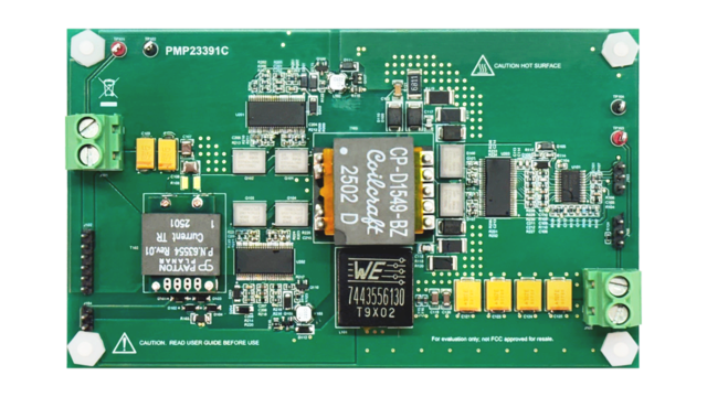 Top of Board
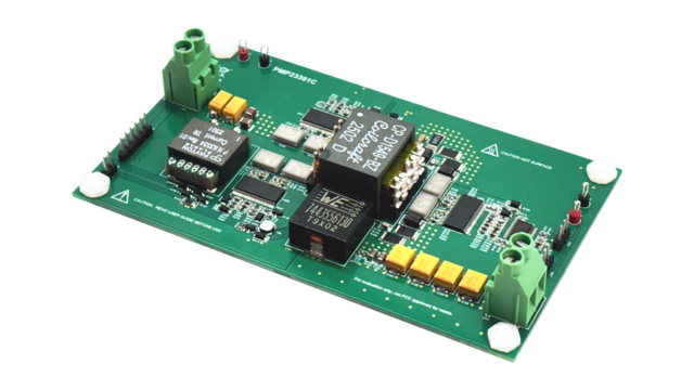 Angled Image
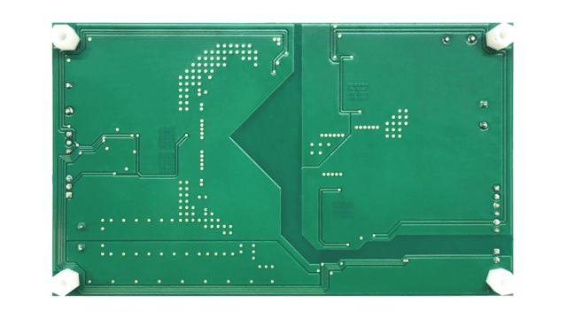 Bottom of Board
1 Test Prerequisites
1.1 Voltage and Current Requirements
| Parameter | Specifications |
|---|---|
| Input voltage | 22V to 36V |
| Output voltage | 12V |
| Maximum output current | 25V |
| Switching frequency | 500kHz (primary side) |
1.2 Considerations
- Unless noted, all tests were conducted with 25A loading on the output
- Local airflow used
- External 12V bias applied to primary and secondary sides
1.3 Dimensions
1.4 Test Setup
Air flow is recommended to test at full load conditions. Thermal image shows relative temperature rise across the PCBA.
 Figure 1-1 Test Setup
2 Testing and Results
2.1 Efficiency Graphs
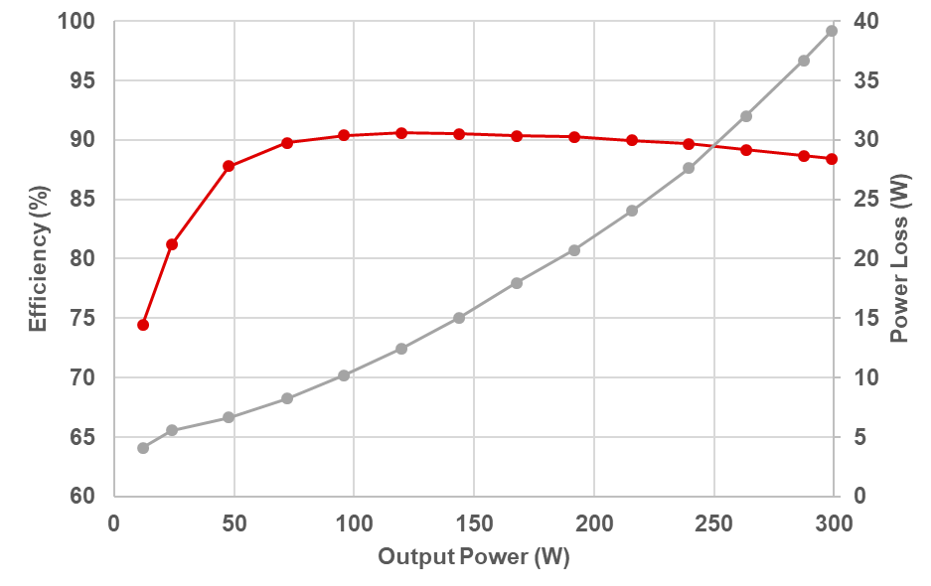 Figure 2-1 Efficiency and Power Loss
With Nominal Input (28V)
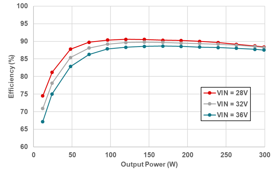 Figure 2-2 Efficiency Across Input
Range
Figure 2-2 Efficiency Across Input
Range2.2 Efficiency Data
| Input | Output | Total | |||||
|---|---|---|---|---|---|---|---|
|
Voltage (V) |
Current (A) |
Power (W) |
Voltage (V) |
Current (A) |
Power (W) |
Loss (W) |
Efficiency (%) |
|
27.994 |
0.572 |
16.012 |
12.01 |
0.993 |
11.926 |
4.086 |
74.481 |
|
27.991 |
1.0557 |
29.551 |
12.009 |
1.998 |
23.994 |
5.557 |
81.195 |
|
27.99 |
1.9498 |
54.57 |
12.006 |
3.99 |
47.904 |
6.666 |
87.784 |
|
27.988 |
2.8657 |
80.21 |
12.004 |
5.997 |
71.988 |
8.222 |
89.749 |
|
27.985 |
3.791 |
106.1 |
12.001 |
7.99 |
95.888 |
10.212 |
90.375 |
|
27.983 |
4.727 |
132.26 |
11.999 |
9.983 |
119.786 |
12.474 |
90.569 |
|
27.979 |
5.68 |
158.91 |
11.996 |
11.991 |
143.844 |
15.066 |
90.519 |
|
27.979 |
6.636 |
185.68 |
11.993 |
13.985 |
167.722 |
17.958 |
90.329 |
|
27.984 |
7.588 |
212.34 |
11.991 |
15.979 |
191.604 |
20.736 |
90.235 |
|
27.986 |
8.564 |
239.66 |
11.988 |
17.988 |
215.640 |
24.020 |
89.978 |
|
27.985 |
9.544 |
267.11 |
11.986 |
19.981 |
239.492 |
27.618 |
89.661 |
|
27.983 |
10.555 |
295.36 |
11.983 |
21.976 |
263.338 |
32.022 |
89.158 |
|
27.976 |
11.582 |
324.01 |
11.98 |
23.984 |
287.328 |
36.682 |
88.679 |
|
27.978 |
12.095 |
338.38 |
11.979 |
24.974 |
299.164 |
39.216 |
88.411 |
|
Input |
Output |
Total |
|||||
|---|---|---|---|---|---|---|---|
|
Voltage (V) |
Current (A) |
Power (W) |
Voltage (V) |
Current (A) |
Power (W) |
Loss (W) |
Efficiency (%) |
|
31.946 |
0.5264 |
16.816 |
12.009 |
0.993 |
11.925 |
4.891 |
70.914 |
|
31.942 |
0.9616 |
30.714 |
12.008 |
1.998 |
23.992 |
6.722 |
78.114 |
|
31.941 |
1.7566 |
56.106 |
12.005 |
3.99 |
47.900 |
8.206 |
85.374 |
|
31.939 |
2.5581 |
81.703 |
12.003 |
5.998 |
71.994 |
9.709 |
88.117 |
|
31.937 |
3.3671 |
107.53 |
12.001 |
7.991 |
95.900 |
11.630 |
89.184 |
|
31.935 |
4.1841 |
133.62 |
11.998 |
9.984 |
119.788 |
13.832 |
89.648 |
|
31.932 |
5.0176 |
160.22 |
11.996 |
11.992 |
143.856 |
16.364 |
89.787 |
|
31.929 |
5.8563 |
186.99 |
11.993 |
13.987 |
167.746 |
19.244 |
89.709 |
|
31.928 |
6.706 |
214.1 |
11.991 |
15.98 |
191.616 |
22.484 |
89.498 |
|
31.931 |
7.557 |
241.3 |
11.988 |
17.988 |
215.640 |
25.660 |
89.366 |
|
31.934 |
8.408 |
268.51 |
11.986 |
19.982 |
239.504 |
29.006 |
89.198 |
|
31.935 |
9.274 |
296.16 |
11.983 |
21.976 |
263.338 |
32.822 |
88.918 |
|
31.933 |
10.167 |
324.67 |
11.981 |
23.984 |
287.352 |
37.318 |
88.506 |
|
31.932 |
10.618 |
339.05 |
11.979 |
24.974 |
299.164 |
39.886 |
88.236 |
|
Input |
Output |
Total |
|||||
|---|---|---|---|---|---|---|---|
|
Voltage (V) |
Current (A) |
Power (W) |
Voltage (V) |
Current (A) |
Power (W) |
Loss (W) |
Efficiency (%) |
|
35.947 |
0.4923 |
17.696 |
12.009 |
0.99 |
11.889 |
5.807 |
67.184 |
|
35.944 |
0.8883 |
31.928 |
12.008 |
1.994 |
23.944 |
7.984 |
74.994 |
|
35.942 |
1.6079 |
57.79 |
12.006 |
3.987 |
47.868 |
9.922 |
82.831 |
|
35.941 |
2.3199 |
83.378 |
12.003 |
5.994 |
71.946 |
11.432 |
86.289 |
|
35.941 |
3.0358 |
109.11 |
12.001 |
7.987 |
95.852 |
13.258 |
87.849 |
|
35.938 |
3.7726 |
135.58 |
11.998 |
9.98 |
119.740 |
15.840 |
88.317 |
|
35.937 |
4.519 |
162.4 |
11.996 |
11.989 |
143.820 |
18.580 |
88.559 |
|
35.934 |
5.2639 |
189.15 |
11.993 |
13.983 |
167.698 |
21.452 |
88.659 |
|
35.932 |
6.0207 |
216.33 |
11.991 |
15.977 |
191.580 |
24.750 |
88.559 |
|
35.931 |
6.791 |
244 |
11.988 |
17.985 |
215.604 |
28.396 |
88.362 |
|
35.933 |
7.559 |
271.42 |
11.986 |
19.978 |
239.456 |
31.964 |
88.224 |
|
35.935 |
8.322 |
299.06 |
11.983 |
21.971 |
263.278 |
35.782 |
88.035 |
|
35.936 |
9.111 |
327.43 |
11.98 |
23.98 |
287.280 |
40.150 |
87.738 |
|
35.936 |
9.508 |
341.69 |
11.979 |
24.97 |
299.116 |
42.574 |
87.540 |