SLVAEZ3 November 2020 TPS25947 , TPS2595 , TPS2596
Tech Note
Introduction
Communication modules allow for electricity meters to transmit energy readings back to a central data concentrator either through a wireless or wired transmission to eliminate costly on-site readings. To ensure this data transmission functionality does not interfere with the metrology of the electricity meter, many countries have adopted standards such as the IR46 and the Dutch P1 Companion Standard to specify protection requirements with regards to the external communications module. To comply with these standards, TI eFuses can be used to provide a low cost and compact solution to meet the different protection requirements that exist around the world.
Common Smart eMeter Topologies
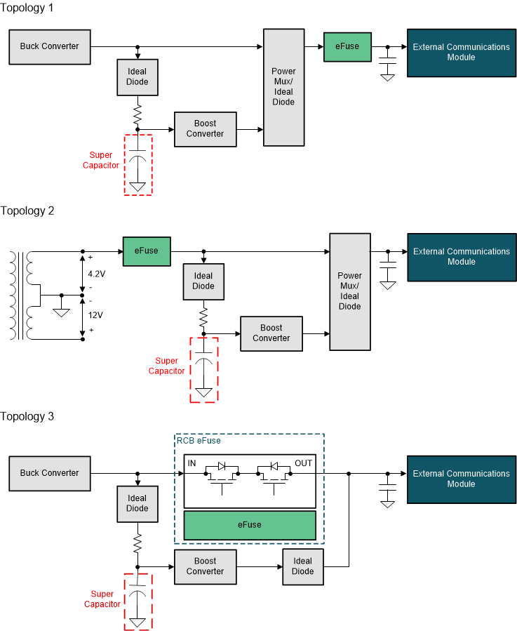
 Figure 1-1 Common smart eMeter
topologies.
 During a power outage, the emeter must also be able to switchover to a super capacitor to provide a “last gasp” transmission to record the latest energy usage and to alert the grid of the outage. For topologies 1 and 2, the power MUX and ideal diode block provides robust reverse current blocking, preventing current from flowing back into the meter while the power path switches to the super capacitor.
Similarly in topology 3, TI also offers integrated eFuse solutions with a back for robust reverse current blocking. An integrated eFuse with reverse current blocking such as the TPS25947 simplifies power path designs for the external communications module.
Benefits of eFuse and its Protection Functions
TI eFuses offer compact, low RON solutions with multiple protection functions such as:
- Overvoltage protection (OVP)
- Current limiting (ILIM)
- Inrush current control (dv/dt)
- Reverse current blocking (RCB)
Depending on the topology that is used some or all of these protection functions could be required. eFuses offer the flexibility of having each of these protection functions in a single, low-cost device so it can be used in multiple designs. Table 1-1 highlights TI’s recommended eFuse devices for emeter applications based on the different protection functions that may be required.
Overvoltage Protection
Topology 2 highlights an emeter architecture where power is derived from two different tap points off of an AC/DC. In this scenario, there is a potential for overvoltage transients to damage the system. Having a solution to detect the overvoltage and limit it is important. TI eFuses offer overvoltage protection to provide this function. Depending on the eFuse it can have two options; overvoltage clamping or overvoltage cutoff.
Overvoltage clamping will clamp the output to a certain voltage until the device reaches the thermal shutdown threshold which will in turn disable the device to protect itself from being damaged due to overheating. Overvoltage cutoff on the other hand will immediately disable the eFuse when the overvoltage threshold is reached to protect the downstream components.
Current Limiting and Short-Circuit Protection
The external connector of the communication module introduces a number of scenarios that could cause short-circuit or overcurrent events in a system such as damaged cabling or connectors, meter tampering, or water and humidity seepage.
Should any of the above scenarios occurs, it is important that the meteorology portion of the system remains functional so the emeter can continue to log the energy usage of the unit and there is no loss in billing.
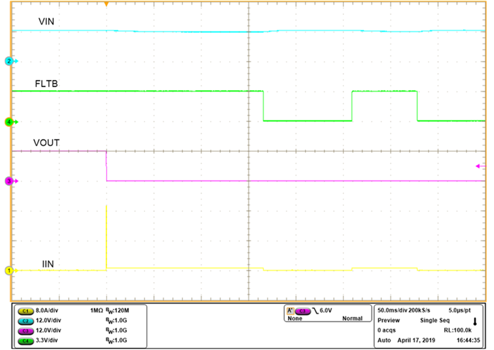
TI eFuses offer adjustable short-circuit and current limiting functions to protect the emeter from these external faults. Short-circuit and current limiting levels can be adjusted to fit the needs of the different communication protocol. Figure 1-2 shows the performance of the fast-trip short-circuit protection of TPS2596 when the output experiences a hot short.
 Figure 1-2 Short-Circuit Response of
TPS2596.
 Inrush Current Control
As mentioned previously, inrush
current control is important to charge up the large bulk capacitance that can sit on
the input of the communications module. TI eFuses have adjustable slew rate control
which allows the user to program the output slew rate of the device to linearly
control the amount of inrush current
(I = C × dv/dt)
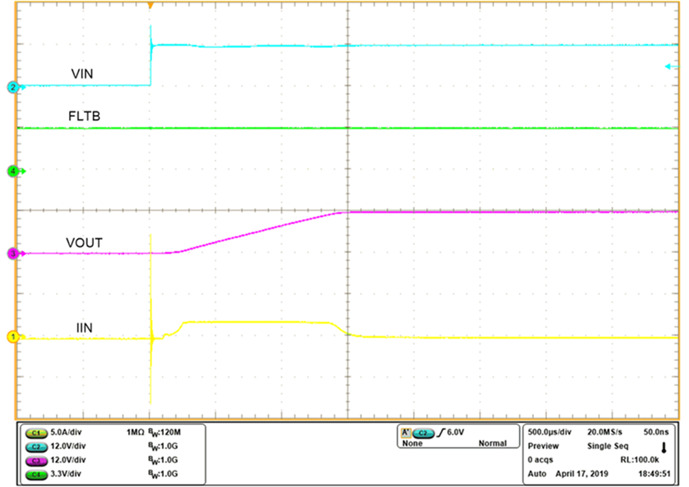
when the module initially powers up. Figure 1-3 shows how the
TPS2596 controls the inrush current when powering up a 220-μF capacitor on its
output.
 Figure 1-3 Inrush Current Hotplug
Response of TPS2596.
 Conclusion
TI eFuses offer an integrated solution for power protection in smart emeters to prevent the system from overvoltage and short-circuit events. Additionally, TI eFuses have low RON which minimizes the voltage drop on the power path to stay within the tight voltage tolerance of the external communications module. Without proper power protection, both the emeter and the external communications module are susceptible to common fault events which can permanently damage the whole system which can result in energy billings being lost.