• Menu
  • Product
  • Email
  • PDF
  • Order now
  • LIN Protocol and Physical Layer Requirements

    • SLLA383A February   2018  – August 2022 SN65HVDA100-Q1 , SN65HVDA195-Q1 , TLIN1022-Q1 , TLIN1029-Q1 , TLIN2022-Q1 , TLIN2029-Q1 , TMS320F28P550SG , TMS320F28P550SJ , TMS320F28P559SG-Q1 , TMS320F28P559SJ-Q1


  • CONTENTS
  • SEARCH
  • LIN Protocol and Physical Layer Requirements
  1.   Abstract
  2.   Trademarks
  3. 1Introduction
    1. 1.1 LIN Specification Progression
    2. 1.2 Workflow Concept
  4. 2Network Architecture
    1. 2.1 General Layout of the LIN Bus
    2. 2.2 Serial Communication Principles
    3. 2.3 Commander-Responder Principle
    4. 2.4 Message Frame Format
  5. 3Physical Layer Requirements
    1. 3.1 Bus Signaling Fundamentals
    2. 3.2 Pullup Values
    3. 3.3 Threshold Values
    4. 3.4 Bit-Rate Tolerance and Timing Requirements
    5. 3.5 Synchronization and Bit Sampling
    6. 3.6 Duty Cycle
  6. 4Filtering, Distance Limitations, Nodes on Bus
    1. 4.1 EMI and Signal Conditioning
    2. 4.2 ESD and Transients
    3. 4.3 Distance and Node Limitations
  7. 5LIN Transceiver Special Functions
    1. 5.1 Low-Power Modes
      1. 5.1.1 Sleep Mode
      2. 5.1.2 Standby Mode
    2. 5.2 Wakeup
      1. 5.2.1 Pin Wakeup
      2. 5.2.2 LIN Wakeup
      3. 5.2.3 Dominant Timeout
  8. 6Advantages and Disadvantages
  9. 7Conclusion
  10. 8Revision History
  11. IMPORTANT NOTICE
search No matches found.
  • Full reading width
    • Full reading width
    • Comfortable reading width
    • Expanded reading width
  • Card for each section
  • Card with all content


APPLICATION NOTE

LIN Protocol and Physical Layer Requirements

1 Abstract

The Local Interconnect Network (LIN), ISO17897, is a multipoint, low-cost and easily-implemented communication bus in automobiles. It works as a sub-bus for the Controller Area Network in most applications. This application note presents the integral parts of LIN technology, focusing on the LIN transceiver itself, information on the protocol, and the physical layer requirements for real applications.
GUID-B66FA06A-6FB3-499C-AA13-FD6D8EE5D557-low.gifFigure 1-1 LIN Hierarchy Chart

Trademarks

All trademarks are the property of their respective owners.

1 Introduction

The amount of electrical systems and components continue to grow as automobiles become more intelligent, safe, and comfortable. The growth of these components and systems demand a need for communication transceivers, to facilitate their interaction in the most advantageous way possible for manufacturers. LIN was developed to manage communication between these components and systems in an efficient and straightforward fashion, where the bandwidth and versatility of CAN was not needed; though in most instances, it is a sub-bus to the CAN bus.

Figure 1-1 High-Level Application Diagram

1.1 LIN Specification Progression

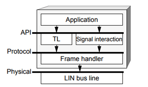
The most up-to-date LIN standard was defined in 2010 (LIN 2.2A, the LIN Consortium). It was then transcribed to the International Organization for Standardization (ISO) to be accepted as ISO 17897 and officially released in 2016. Prior to 2010, LIN went through a series of revisions, being fully defined first in LIN 1.1 (1999), where the LIN Protocol Specification, LIN Configuration Language Specification, and LIN Application Interface Specification were established by a board called the LIN consortium. Each of these are necessary parts in creating the full LIN cluster in a way that is consistent across the market, allowing any car manufacturer to use the communication scheme. The LIN protocol specification describes the physical and data link layers, and the LIN Configuration Language enables the LIN cluster to be described in a file that is straightforward for any developer.


Texas Instruments

© Copyright 1995-2025 Texas Instruments Incorporated. All rights reserved.
Submit documentation feedback | IMPORTANT NOTICE | Trademarks | Privacy policy | Cookie policy | Terms of use | Terms of sale