-
Bidirectional CLLLC Resonant Converter Reference Design for Energy Storage System
- 1
- Description
- Features
- Applications
-
1Test Prerequisites
- 1.1 Voltage and Current Requirements
- 1.2 Required Equipment
- 1.3 Test Setup
- 1.4
Running the Code for Different Labs
- 1.4.1 Lab 1. Primary to Secondary Power Flow, Open Loop Check PWM Driver
- 1.4.2 Lab 2. Primary to Secondary Power Flow, Open Loop CheckPWM Driver and ADC With Protection
- 1.4.3 Lab 3. Primary to Secondary Power Flow, Closed Voltage Loop Check
- 1.4.4 Lab 4. Primary to Secondary Power Flow, Closed Current Loop Check
- 1.4.5 Lab 6. Secondary to Primary Power Flow, Open Loop Check PWM Driver
- 1.4.6 Lab 7. Secondary to Primary Power Flow, Open Loop Check PWM Driver and ADC With Protection
- 1.4.7 Lab 8. Secondary to Primary Power Flow, Closed Voltage Loop Check
- 2Testing and Results
- 3Waveforms
- IMPORTANT NOTICE
Test Report
Bidirectional CLLLC Resonant Converter Reference Design for Energy Storage System
Description
The
capacitor-inductor-inductor-inductor-capacitor (CLLLC) resonant converter with a
symmetric tank, soft switching characteristics, and ability to switch at higher
frequencies is a good choice for energy storage systems. This design illustrates control
of this power topology using a C2000® MCU in closed
voltage and closed current-loop mode. The hardware and software available with this
design help accelerate time to market.
Features
- Vprim: 380–410 V DC; Vsec: 40–60 V DC
- Power Maximum: 3.6 kW, 97.6% peak efficiency
- Soft switching with Zero Voltage Switching (ZVS) on the primary, Zero Current Switching (ZCS), and ZVS on the secondary enable higher efficiency
- Active synchronous rectification scheme implementation using Rogowski coil sensor enables higher efficiency
- Software Frequency Response Analyzer (SFRA) and Compensation Designer for ease of tuning of control loops
- Software support for the TMS320F28004x device with the Control Law Accelerator (CLA), which enables integrated power conversion system design with AC-DC and DC-DC controlled using a single C2000 MCU
Applications
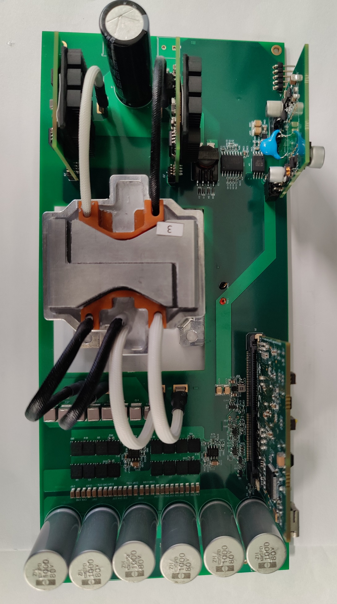
 Top View of Board
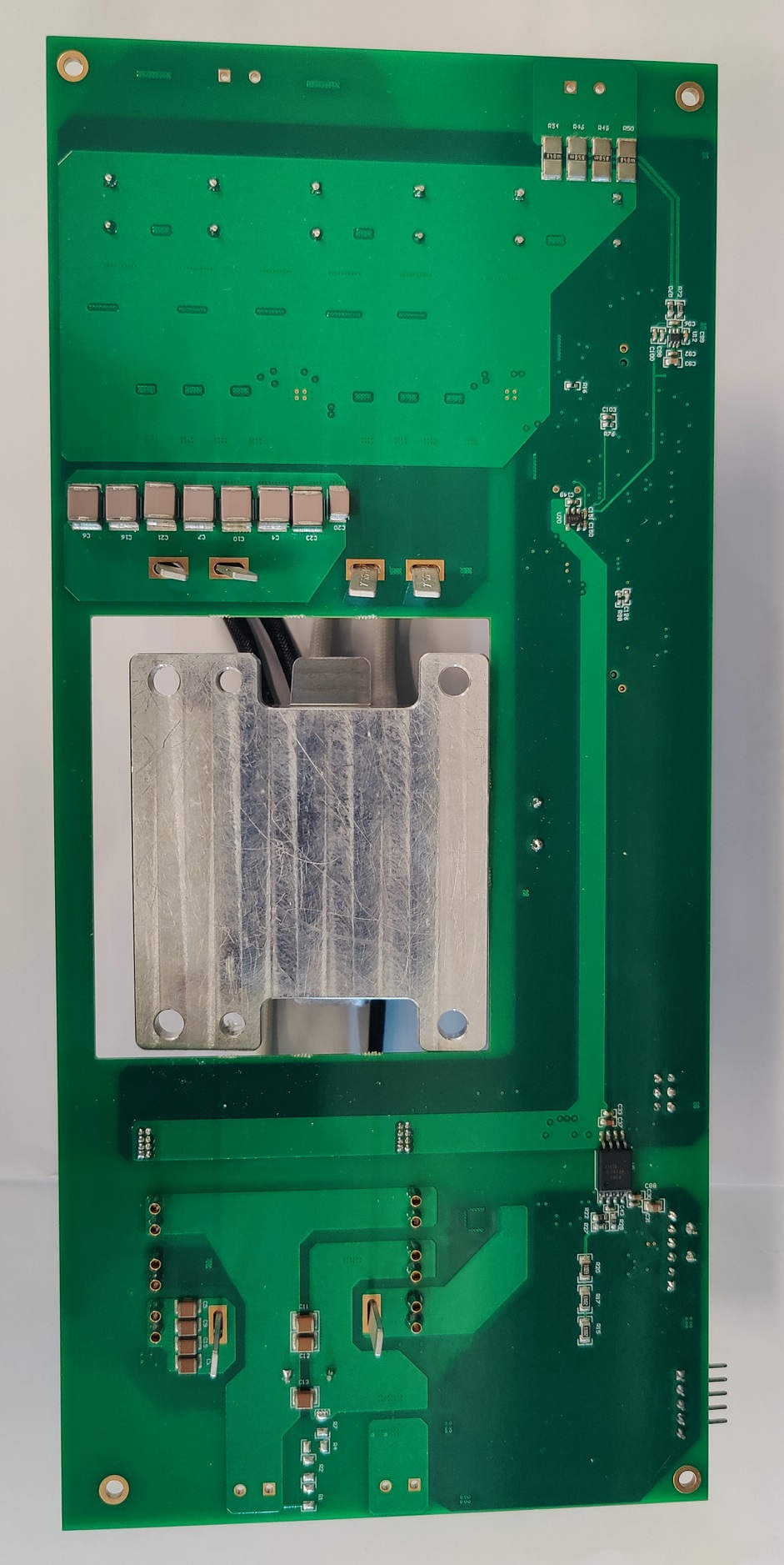
 Bottom View of Board