-
What Happens When Low-voltage BLDC Motors Drive Appliance Subsystems
What Happens When Low-voltage BLDC Motors Drive Appliance Subsystems
Renton Ma

Given their high efficiency, lower audible noise and long life cycles, brushless DC (BLDC) motors are widely used in household appliance subsystems such as refrigerator, dishwasher and washing machine fans and pumps. These subsystems usually require less than 100W of output power for the motor and are typically driven by high DC voltages (over 150/300V) derived from the 110/230VAC mains. In this blog post, I’ll discuss an alternative solution for driving appliance subsystems using a low-voltage (typically 24V) motor drive.
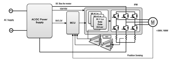
For high-voltage motors, the AC mains supply is rectified to get the high-voltage DC bus, which drives the inverter stage consisting of discrete insulated-gate bipolar transistors (IGBTs), MOSFETs or integrated power modules (IPMs). The system usually requires a bias power supply to provide 5VDC or 3.3VDC supplies to the controller units and 12V or 15V for the gate driver. Figure 1 shows the typical block diagram of a high-voltage motor-control system.
 Figure 1 System Block Diagram for a
High-voltage Motor Control System
Figure 1 System Block Diagram for a
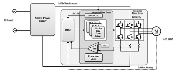
High-voltage Motor Control SystemIn low-voltage DC motor-drive systems, the AC/DC power-supply unit generates a lower DC bus voltage (such as 24V) with the required output-power capability. The power stage uses this low DC bus voltage to drive the motor. Using voltage regulators enables the AC/DC power-supply unit to derive the required bias power supplies.
Figure 2 shows the typical block diagram of a low-voltage motor-control system.
 Figure 2 System Block Diagram for a
Low-voltage Motor-control System
Figure 2 System Block Diagram for a
Low-voltage Motor-control SystemHere are some benefits of low-voltage motor-control systems:
- Safety. The most obvious benefit of low-voltage motors is that they make systems safer for maintenance service personnel and designers. Moving pumps and fans to a low voltage keeps the major part of the system isolated from the high-voltage input.
- Integration level. The latest low-voltage motor controller integrated circuits (ICs) are highly integrated, with features like cycle-by-cycle overcurrent protection, overtemperature protection, stall detection, auto dead-time insertion, and slew-rate control. Some driver ICs are equipped with linear or switching voltage regulators, operation amplifiers for shunt current sensing, power stages and embedded control algorithms. Highly integrated drivers like the TI DRV10983 three-phase sensorless BLDC motor controller integrate the MOSFET’s gate driver and control algorithm into a single IC, and implement sinusoidal current control without any current-shunt resistors.
- Shorter design cycle. With such a high integration level, using an advanced low-voltage BLDC motor-driver IC may significantly reduce the subsystem’s design cycle. For example, using the DRV10983 for a fan control subsystem design does not require any software effort on the motor-control algorithm. You would only need to tune the motor parameters via the I2C communication interface to the controller IC and start evaluating.
- Flexibility. You can use low-voltage motors and drives for either 110V or 220V line-input operation using a universal input AC/DC converter. The low-voltage motor drive sub-system is easily adaptable into battery and/or solar-powered systems. This gives the benefit of using a single motor and controller platform for a wide number of systems.
- Size and cost. Low-voltage motor-control ICs are usually with much smaller packages compared to high-voltage IPMs, given the different technologies used and the low clearance and creepage distance requirements. While designing the printed circuit board (PCB), the high-voltage area on the board usually requires more clearance, creepage distance and care for isolation than the low-voltage area, which could result in a larger board size. In low-voltage low-power applications, even with higher current, the optimized RDSON and the gate charge of the MOSFET help achieve very low FET losses. With optimized thermal management, the power stage may not require extra heat-dissipation components, thus saving on overall system cost.
- Audible noise. Audible noise generated by electric motors is a result of the motor-output torque ripple. The six-step commutation-based trapezoidal control in BLDC motors can create commutation torque ripple and hence audible noise. The sinusoidal current in motor winding, along with sinusoidal back electromotive force (EMF), will ideally give zero torque ripple. The DRV10983 with sinusoidal current output helps achieve very low audible noise.
However, using low-voltage BLDC motors in the system requires a power supply capable of providing a low-voltage DC output to power the motor drive.
AC/DC Converter
To address the challenge of using low-voltage motors, the TI Designs 150W High Efficiency Primary Side Regulated DCM/CCM Flyback Supply Reference Design features a 24V, 12V output, 150W isolated primary-side regulation (PSR) flyback controller-based power supply, with built-in protections for overcurrent, overvoltage, feedback-loop open/short detection, overtemperature, overload timer, AC line undervoltage and brownout. PSR helps eliminate the need for secondary-side feedback and regulation components and an optocoupler, enabling cost optimization and increasing reliability. The additional 12V can power up the gate drivers and generate the bias power supplies.
Figure 3 shows the block diagram of the 150W PSR flyback power supply. The power supply is designed and tested for a universal input AC range from 85-270VAC. The electromagnetic interference (EMI) filter at the front end of the circuit is designed to meet EN55011 Class A conducted emission levels. The design achieves low standby power of 200mW at 230VAC.
 Figure 3 150W PSR Flyback Power Supply Block Diagram
I hope you now understand the benefits of a low-voltage BLDC drive for low-power applications in terms of safety, integration, size, cost and design-cycle reduction, especially compared to a high-voltage system.
Additional Resources
- See the Appliances applications page for more design information.
- Check out these TI Designs reference designs:
- The 24V Dual Brushless DC Motor Drive Reference Design for Major Home Appliances uses the DRV8303 and DRV10983 on the same board.
- Mains Operated, 24V, 30W BLDC Motor Drive with Highly Efficient, High Power Factor Power Supply.
- Current Controlled Driver for 230V AC Solenoids Reference Design.
- Offline AC/DC 120W Multioutput Flyback Power Supply Reference Design.
- Learn more about an even lower-power-level design reference.
IMPORTANT NOTICE AND DISCLAIMER
TI PROVIDES TECHNICAL AND RELIABILITY DATA (INCLUDING DATASHEETS), DESIGN RESOURCES (INCLUDING REFERENCE DESIGNS), APPLICATION OR OTHER DESIGN ADVICE, WEB TOOLS, SAFETY INFORMATION, AND OTHER RESOURCES “AS IS” AND WITH ALL FAULTS, AND DISCLAIMS ALL WARRANTIES, EXPRESS AND IMPLIED, INCLUDING WITHOUT LIMITATION ANY IMPLIED WARRANTIES OF MERCHANTABILITY, FITNESS FOR A PARTICULAR PURPOSE OR NON-INFRINGEMENT OF THIRD PARTY INTELLECTUAL PROPERTY RIGHTS.
These resources are intended for skilled developers designing with TI products. You are solely responsible for (1) selecting the appropriate TI products for your application, (2) designing, validating and testing your application, and (3) ensuring your application meets applicable standards, and any other safety, security, or other requirements. These resources are subject to change without notice. TI grants you permission to use these resources only for development of an application that uses the TI products described in the resource. Other reproduction and display of these resources is prohibited. No license is granted to any other TI intellectual property right or to any third party intellectual property right. TI disclaims responsibility for, and you will fully indemnify TI and its representatives against, any claims, damages, costs, losses, and liabilities arising out of your use of these resources.
TI’s products are provided subject to TI’s Terms of Sale (www.ti.com/legal/termsofsale.html) or other applicable terms available either on ti.com or provided in conjunction with such TI products. TI’s provision of these resources does not expand or otherwise alter TI’s applicable warranties or warranty disclaimers for TI products.
Mailing Address: Texas Instruments, Post Office Box 655303, Dallas, Texas 75265
Copyright © 2023, Texas Instruments Incorporated