• Menu
  • Product
  • Email
  • PDF
  • Order now
  • ONET1130EC-EVM 11.7-Gbps transceiver with dual CDRs and modulator driver

    • SNLU245 February   2019 ONET1130EC


  • CONTENTS
  • SEARCH
  • ONET1130EC-EVM 11.7-Gbps transceiver with dual CDRs and modulator driver
  1.   ONET1130EC-EVM 11.7-Gbps transceiver with dual CDRs and modulator user’s guide
    1.     Trademarks
    2. 1 Hardware and Equipment
    3. 2 EVM Block Diagram
    4. 3 EVM Connections
    5. 4 Measurement Setup
      1. 4.1 USB2ANY GUI Installation
      2. 4.2 Open-Loop Operation Without Fault Detection or Digital Monitoring
      3. 4.3 Closed-Loop Operation With Fault Detection and Digital Monitoring
    6. 5 LED Indicators
    7. 6 Typical Performance Results
    8. 7 Schematics
    9. 8 ONET1130EC-EVM PCB Layout
    10. 9 Bill of Material
  2. IMPORTANT NOTICE
search No matches found.
  • Full reading width
    • Full reading width
    • Comfortable reading width
    • Expanded reading width
  • Card for each section
  • Card with all content


EVM USER'S GUIDE

ONET1130EC-EVM 11.7-Gbps transceiver with dual CDRs and modulator driver

ONET1130EC-EVM 11.7-Gbps transceiver with dual CDRs and modulator user’s guide

This document describes the main features and functionality of the evaluation module (EVM) board for the part numbers ONET1130EC and ONET1130EP.

The ONET1130EC and ONET1130EP are 11.7-Gbps transceivers with integrated limiting amplifier and modulator driver. The ONET1130EC includes dual CDRs and the ONET1130EP does not.

The EVM can be used to evaluate the performance of the parts in conjunction with an electroabsorptive modulated laser (EML) transmit optical subassembly (TOSA) and a receive optical subassembly (ROSA) in standard XMD compliant packages.

The EVM is controlled with USB2ANY graphic user interface (GUI). This software can be downloaded at www.ti.com.
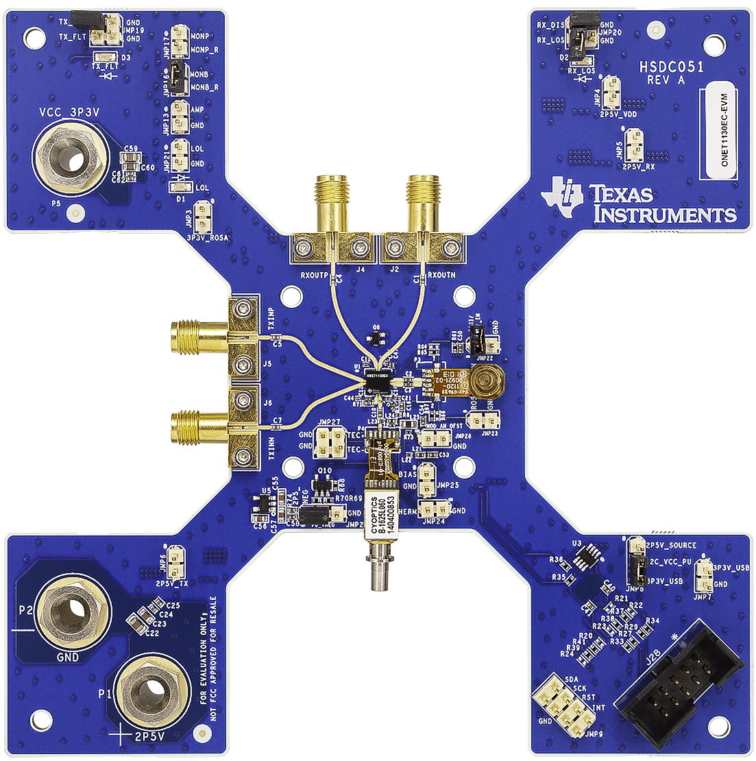
HSDC051-EVM-SH-V6356-96ppi.pngFigure 1. ONET1130EC-EVM

Trademarks

All trademarks are the property of their respective owners.

1 Hardware and Equipment

The following hardware and equipment are required to evaluate the EVM:

  • An ONET1130EC-EVM
  • An XMD-compliant EML TOSA
  • An XMD-compliant PIN or APD ROSA
  • TI USB2ANY Interface Adaptor
  • TI USB2ANY Explorer Software
  • A USB cable with standard-A to Mini-B connector
  • A PC with a USB A port
  • RF cables with SMA connectors
  • External thermoelectric controller
  • Single-mode fiber patch cords
  • Electrical cables with banana jack connections

2 EVM Block Diagram

Figure 2 represents the block diagram of the ONET1130EC-EVM. The board is designed to be powered from a 2.5-V supply using cables with banana jacks.

ONET1130EC-BLK.gifFigure 2. ONET1130EC-EVM Block Diagram


Texas Instruments

© Copyright 1995-2025 Texas Instruments Incorporated. All rights reserved.
Submit documentation feedback | IMPORTANT NOTICE | Trademarks | Privacy policy | Cookie policy | Terms of use | Terms of sale