-
Implementing Programmability and Diagnostics With the TMAG5328 Resistor and Voltage Programmable Hall-Effect Switch
Implementing Programmability and Diagnostics With the TMAG5328 Resistor and Voltage Programmable Hall-Effect Switch
Abstract
This application note discusses how the TMAG5328 resistor and voltage adjustable, low-power Hall-effect switch can increase system design flexibility and reduce design time. In addition, the document also discusses how using voltage to adjust the TMAG5328’s BOP enables multiple applications. One of these applications is a software programmable Hall-effect switch with microcontroller-less standalone mode, which is done by using a DAC or digital potentiometer with nonvolatile memory. Additionally, the document discusses how sweeping the voltage that sets the BOP can be used to back-calculate the sensed magnetic flux density seen by the TMAG5328. This document also discusses how adding a square wave voltage waveform can help the TMAG5328 implement diagnostics for detecting faults such as TMAG5328 device pin shorts, TMAG5328 device pin disconnections, and when a system’s magnet is either too close or too far from the sensor. The magnet out-of-range functionality implemented for diagnostics can also be reused as a magnetic window comparator instead.
Trademarks
All trademarks are the property of their respective owners.
1 Introduction
Many systems require a mechanism to detect the mechanical position between a moving component in the system and a fixed component. Systems that only require a simple binary detection of position are often implemented by placing a magnet on the movable component and a Hall-effect switch on the fixed component (the base). An example of an open/close detection system is the mechanism in refrigerators that detect when the refrigerator’s door (the moving component) is open or closed, which determines when to turn ON or OFF the refrigerator light. In Figure 1-1, a magnet is placed on the moving refrigerator door and the Hall-effect switch is placed on a fixed PCB underneath the refrigerator base. In this example, it is assumed that the center of the magnet is directly above the sensing element of the Hall sensor when the refrigerator door is closed.
Figure 1-1 Example Open/Close Detection System With Hall-Effect Sensors and Magnet.
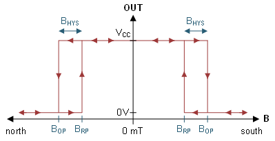
Figure 1-2 shows an example output graph of the TMAG5328 omnipolar Hall-effect switch. The device in Figure 1-2 is an omnipolar device, therefore the output responds to both positive and negative magnetic flux densities, which means the device responds the same regardless if the north or south pole of a magnet approaches the device. As the magnet approaches the Hall-effect switch, the magnitude of the sensed magnetic flux density increases. When the applied magnetic flux density exceeds the BOP threshold, the device in Figure 1-2 outputs a low voltage. The output of the device in Figure 1-2 stays low until the magnetic flux density decreases to less than BRP, and then the output drives a high voltage.
 Figure 1-2 Output Graph of the
TMAG5328 Omnipolar Switch.
 1.1 Mapping Switching Distance to Magnetic Flux Density
The relationship between the sensed magnetic flux density and the magnet-to-sensor distance along with the BOP and BRP determine the magnet-to-sensor distance at which the switch changes state. In many cases, the magnet travels in a direct linear path of travel, so distance is often expressed by the direct magnet-to-sensor distance. In Figure 1-1, however, distance is specified by the angle of opening because the refrigerator door opens on a hinge that causes the magnet to move nonlinearly. For Figure 1-1, the magnet-to-sensor distance increases as the angle of opening increases.
Figure 1-3 shows an example graph of how the sensed magnetic flux density varies as the angle of the opened refrigerator door 1 varies. The magnet-to-sensor distances at which the switch changes state depends on the BOP and BRP. If you want to determine the typical distance at which the sensor switches state, find the locations on the Figure 1-3 plot where the sensed magnetic flux density values are equal to the BOP,TYP and BRP,TYP specifications listed in the device data sheet. Alternatively, when determining the worst-case device to device variation for output switching, refer to the BOP,Max and BRP,Min specifications. BOP,Max and BRP,Min account for process variation, temperature and voltage. Designing the system within these bounds will result with consistent operation despite these variables.
As an example, let’s say there are two Hall-effect switches with the following specs:
Switch 1
BRP,MIN =5.12 mT
BRP,TYP =6.87 mT
BOP,TYP =7.87 mT
BOP,MAX =9.62 mT
Switch 2
BRP,MIN =0.73 mT
BRP,TYP =1.58 mT
BOP,TYP =2.58 mT
BOP,MAX =3.43 mT
If switch 1 is used in refrigerator 1, the output of switch 1 will be low when the angle of opening for door 1 is ≤1.8°, regardless of variations in process variation, temperature, and voltage. The angle of opening for door 1 is ≤1.8° when the sensed magnetic flux density is greater than the 9.62 mT BOP,MAX. However, the typical distance where the output of switch 1 is asserted low would be at 2°, which is when the sensed magnetic flux density equals the device’s BOP,TYP value of 7.87 mT. The output of switch 1 will be high when angle of opening for door 1 is ≥2.5°, which is when the sensed magnetic flux density is less than the 5.12 mT BRP,MIN. The typical distance where the output of switch 1 is asserted high, however, would be at 2.2°.
If switch 2 is used in refrigerator 2, the typical distance at which the output of switch 2 is asserted low would be at 3.5°. The output would be low at an angle ≤3.1° regardless of variations in process variation, temperature, and voltage. Additionally, the output of switch 2 would be asserted high at 4.4° typically. The output would be asserted high at an angle ≥6.0° regardless of variations. The different switching distances of switches 1 and 2 shows how switching distance is dependent on the BOP and BRP specs of a Hall sensor.