SLAAEA0 March 2023 MSPM0C1105 , MSPM0C1106 , MSPM0H3216 , MSPM0L1105 , MSPM0L1106 , MSPM0L1303 , MSPM0L1304 , MSPM0L1305 , MSPM0L1306 , MSPM0L1343 , MSPM0L1344 , MSPM0L1345 , MSPM0L1346
Thermometers help us detect and prevent the spread of illness. Digital thermometers have mostly replaced mercury stick thermometers over the past ten to fifteen years as they allow faster, more convenient temperature detection without the risk of the health hazards associated with mercury.
All digital thermometers include two key components: a temperature sensor that outputs a voltage signal based on temperature and a microcontroller (MCU) that converts the voltage signal into a temperature reading. Measurement time, battery life, design size, and cost are key considerations when selecting an MCU for a thermometer design. With their low power, low price, and high-performance features, MSPM0 MCUs are a great choice for digital thermometer designs.
 Figure 1-1 Digital thermometers
Digital thermometer components
Digital thermometers are typically made up of the following components:
- Temperature sensor: The key device that varies electrical signal in response to changes in temperature.
- Operational amplifier (OPA): The device used to condition the signal from the temperature sensor so that it can be easily processed.
- ADC: The component that converts analog signal to a digital signal.
- User interface: Any components that the user interacts with: LCD display, buttons, or LEDs
- Power management: The subsystem responsible for powering the whole thermometer; most commonly includes a battery.
- Microcontroller (MCU): The device responsible for reading and reacting to changes in the signal from the ADC, driving the user interface to display a temperature value, and controlling the power management subsystem.
Why is MSPM0 suitable for digital thermometer designs?
Digital thermometers are expected to be low-cost, long lasting, and small in size; these are all factors enabled by MSPM0 MCUs.
TI’s scalable MSPM0 MCU portfolio features an Arm® Cortex-M0+ core, with a maximum CPU speed of 80-MHz. The pin-to-pin compatible portfolio ranges from 4-KB to 512-KB of flash memory and has a low standby current that enables longer battery life. MSPM0 MCUs feature small footprint packages and optional analog integration that enables high performance, low-cost, and overall flexibility within digital thermometer designs.
Detecting temperature in digital thermometer designs
There are two kinds of digital thermometers on the market: contact thermometers and contactless thermometers.
Contact thermometers
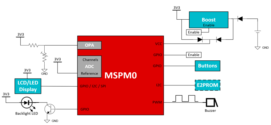
 Figure 1-3 Block Diagram of a Contact Thermometer Based on MSPM0L130x
Contact thermometers are named as such because they require about 20 seconds of continuous contact with the patient to perform temperature detection. Most commonly sold as a digital stick thermometer, these instruments typically use a thermistor as a temperature sensor and have a general accuracy of ± 0.1 °C. The thermistor, a device whose resistance varies in negative correlation with the temperature range, is a popular choice for temperature sensors in contact thermometers due to this application’s small size and narrow temperature range. The thermistor measures temperature by adjusting its resistance in correlation to the surrounding temperature and thus altering the voltage signal. The voltage around the thermistor is conditioned with an OPA and sent to an ADC to be converted into a digital signal. The MCU first converts the digital signal into a readable temperature using a programmed lookup-table and then communicates with the user interface components to display the temperature.
Some components, such as the OPA and ADC, are often integrated into the MCU to save on overall cost and board space. The optimized analog integration and small footprint packages available with MSPM0 MCUs makes it possible to have a device that is both high performance and low-cost.
Contactless thermometers
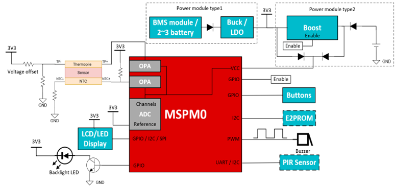
 Figure 1-4 Block Diagram of a Contactless Thermometer Based on MSPM0L130x
Contactless thermometers, like infrared ear and forehead thermometers, are designed to detect temperature in about 1 second without ever needing to come in physical contact with the patient. These instruments use a single pixel thermopile sensor to detect temperature. Thermopile sensors focus infrared radiation from the human body onto an internal negative-temperature-coefficient thermistor (NTC) that reacts to the temperature by adjusting its resistance accordingly. The voltage signal from the thermistor is then conditioned with an OPA and converted to a digital signal by an ADC. Finally, the MCU calculates a temperature value based on the programmed lookup-table and drives the user interface to display the reading.
Similar to the contact thermometer, the integrated analog and small packages available in the MSPM0 portfolio make these MCUs are a great fit for contactless thermometer designs.
Key features of MSPM0 suited for digital thermometer designs
The main requirements for an MCU in contact thermometers are low power consumption to ensure long battery life and integrated analog that enables small design. MSPM0 MCUs meet these requirements with the following available features:
- Low working voltage: The 1.62-V lowest working voltage of the MSPM0 MCUs can enable a longer product life.
- Low-power mode: MSPM0 supports low-power mode operation with a standby current of 1uA and can therefore help increase a product’s working life.
- 12-bit ADC: With up to 128 times hardware oversampling, the integrated 12-bit ADC available on MSPM0 MCUs can achieve 14-bit effective and detect lower than 1-mV change.
- Zero-drift chopper OPAs: With 2 µVpp 1/f noise, 60-µV offset, and ±1-µV/°C drift, the internal OPA achieves high temperature resolution while saving BOM cost and PCB space
MSPM0 function examples
The following is a list of function examples of how MSPM0 can be used in digital thermometer designs.
- Calibrate for thermistor or thermopile
- Configure ADC and OPAs to capture and condition temperature sensor voltages
- Program a lookup-table to quickly calculate temperature from input voltage
- Monitor battery
- Control LED backlight and LCD/LED display
Resources
Order an MSPM0 LaunchPad development kit today to start evaluating MSPM0 for your thermometer system. Jump start your thermometer design with MSPM0 code examples and interactive online training. You can also find other resources under these links: