-
Choose the Best out of Three Ultra-Low-Power Architectures for Your Wireless Sensor Tags and Data Loggers
Choose the Best out of Three Ultra-Low-Power Architectures for Your Wireless Sensor Tags and Data Loggers
Trademarks
SimpleLink, SmartRF, BoosterPack, and EnergyTrace are trademarks of Texas Instruments Incorporated.
Arm, Cortex, are registered trademarks of Arm Limited.
All trademarks are the property of their respective owners.
1 Introduction
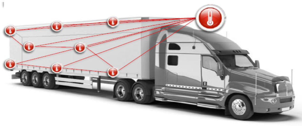
A wireless sensor tag for asset tracking monitors temperature, humidity, ambient light or other environmental parameters and typically transmits the data over a low-power short-range wireless network to a gateway. Support for global cold chain requires proper handling of time- and temperature-sensitive shipments and enables remote control for food, pharmaceuticals and other cargo with similar shipping requirements.
 Figure 1-1 Sensor Tags Application in
Cold Chain
Figure 1-1 Sensor Tags Application in
Cold ChainIn the application illustrated in Figure 1-1, the key functions are the readout of the various sensors as well as providing low power wireless connectivity in either Sub-1 GHz, 2.4 GHz or both RF bands. Ultra-low power dual-band wireless MCUs, such as the CC1352P device, integrate the function of a general-purpose microcontroller, a dedicated sensor controller engine peripheral, and wireless connectivity into a single device.
There are two traditional solutions for low-power sensing applications: most common is the standard Standby approach, where the MCU is running in a low-power mode when not accessing the sensor device, by maintaining a Real Time Clock (RTC) and its RAM contents all the time.
The second solution is the Duty-cycle approach, where the full system power is being switched on and off between two sensor readout cycles and the MCU loses its RAM and RTC contents, while a nano-timer device keeps track of the duty-cycle period. This method achieves ultra-low power in the switched-off (power-off) state, typically in the range of 50 nA, as documented in Humidity and Temp Sensor Node for Sub-1GHz Star Networks Enabling 10+ Year Coin Cell Battery Life.
This report introduces a new solution, also called the Sensor Controller approach, which is a combination of the standard and duty-cycle methods, with the following functionalities:
- The CC1352P MCU runs in standby mode, directly powered by the battery. Thus no external devices, such as a nano-timer and an ultra-low leakage load switch, are required.
- The Sensor Controller Engine (SCE) peripheral implements the I2C communication and data transfer to and from the sensor (in contrast to the other two solutions, where this task is handled by the main Arm®Cortex®-M4F MCU core).
- Using one general purpose IO pin, the SCE powers off the two pullup resistors for the SCL and SDA lines when the sensor is off and no I2C communication is running.
- SCE stores the sensor data in a user-configurable buffer (up to 3K bytes long) while in standby and passes a chunk of this buffer data at once to the Arm Cortex-M4F core.
- The Arm Cortex-M4F core creates a data packet with a user-configurable payload length as per the data protocol being used, and sends it over-the-air.
- Optional: Using one general-purpose IO pin, the SCE powers on or off the sensor device (depends on duty-cycle of the sensor readout).
Figure 1-2 shows the block diagram of the Sensor Controller (or SCE-based) approach. Note that even though this diagram looks identical to the popular Standby method, there are hardware differences to consider, due to the dedicated SCE ultra-low power peripheral handling the I2C protocol autonomously. Two dedicated IO pins are used to deliver the power supply to the sensor (here the HDC2010 device) and the I2C pullup resistors. These IO pins, controlled by the SCE, enable the duty-cycling of both the sensor power supply pin (if needed) and the resistors, leading to a truly optimized low-power solution.
 Figure 1-2 SensorTag or Data Logger
Solution for Temperature and Humidity With Ultra-low Power (I2C-bus and GPIO
Pins)
Figure 1-2 SensorTag or Data Logger
Solution for Temperature and Humidity With Ultra-low Power (I2C-bus and GPIO
Pins)This report describes a solution, where the CC1352P device utilizes its Sensor Controller Engine to configure the HDC2010 for reading out temperature and humidity data periodically. This solution can be used as a development platform for both temperature and humidity monitoring or data logger devices. The period for monitoring of the temperature and humidity is configurable and spans from milliseconds to seconds if this is only dependent on the functionality of the HDC2010 or HDC2080 devices, as the CC1352P MCU is continuously powered and runs TI RTOS with a real-time clock. The wake up and sensor readout can occur after any user-defined period, as required by the application.
2 System Overview
2.1 Software
The following software is used to create and work with the Sensor Controller CPU in the CC1352P MCU (these revision numbers are used for performance testing in this document).
- Sensor Controller Studio (SCS) v2.5.0
- Code Composer Studio (CCS) 9.1.0
- SDK3.20.00.20 (SDK for the CC1352P device, code example rfPacketTX)
- SWRC367 Firmware
First, the Sensor Controller code for interfacing to the HDC2010 sensor was developed and verified by reading out manufacturer and vendor ID pre-defined values, as well as monitoring the I2C-bus transactions as Figure 3-3 shows.
Next, the Sensor Controller I2C-bus functions are integrated into the existing rfPacketTX code example from the SDK with a focus on ultra-low power and periodic RF transmissions. All data packets were monitored using a CC1350 LaunchPad under SmartRF™ Studio in "Packet RX" mode to capture and visualize the data content.
Finally, a second CCS project was developed, based on rfPacketTX, now using the main MCU for controlling the HDC2010 device over I2C-bus and leaving the SCE peripheral unused.