• Menu
  • Product
  • Email
  • PDF
  • Order now
  • TPS629xx-Q1 Functional Safety FIT Rate and Pin FMA

    • SFFS465 May   2022 TPS62901-Q1 , TPS62902-Q1 , TPS62903-Q1


  • CONTENTS
  • SEARCH
  • TPS629xx-Q1 Functional Safety FIT Rate and Pin FMA
  1. 1Overview
  2. 2Functional Safety Failure In Time (FIT) Rates
  3. 3Pin Failure Mode Analysis (Pin FMA)
  4. IMPORTANT NOTICE
search No matches found.
  • Full reading width
    • Full reading width
    • Comfortable reading width
    • Expanded reading width
  • Card for each section
  • Card with all content


FUNCTIONAL SAFETY FIT RATE, FMD AND PIN-FMA

TPS629xx-Q1 Functional Safety FIT Rate and Pin FMA

1 Overview

This document contains information for the TPS629xx-Q1 (VQFN package) to aid in a functional safety system design. Information provided are:

  • Functional Safety Failure In Time (FIT) rates of the semiconductor component estimated by the application of industry reliability standards
  • Pin failure mode analysis (Pin FMA)

Figure 1-1 shows the device functional block diagram for reference.
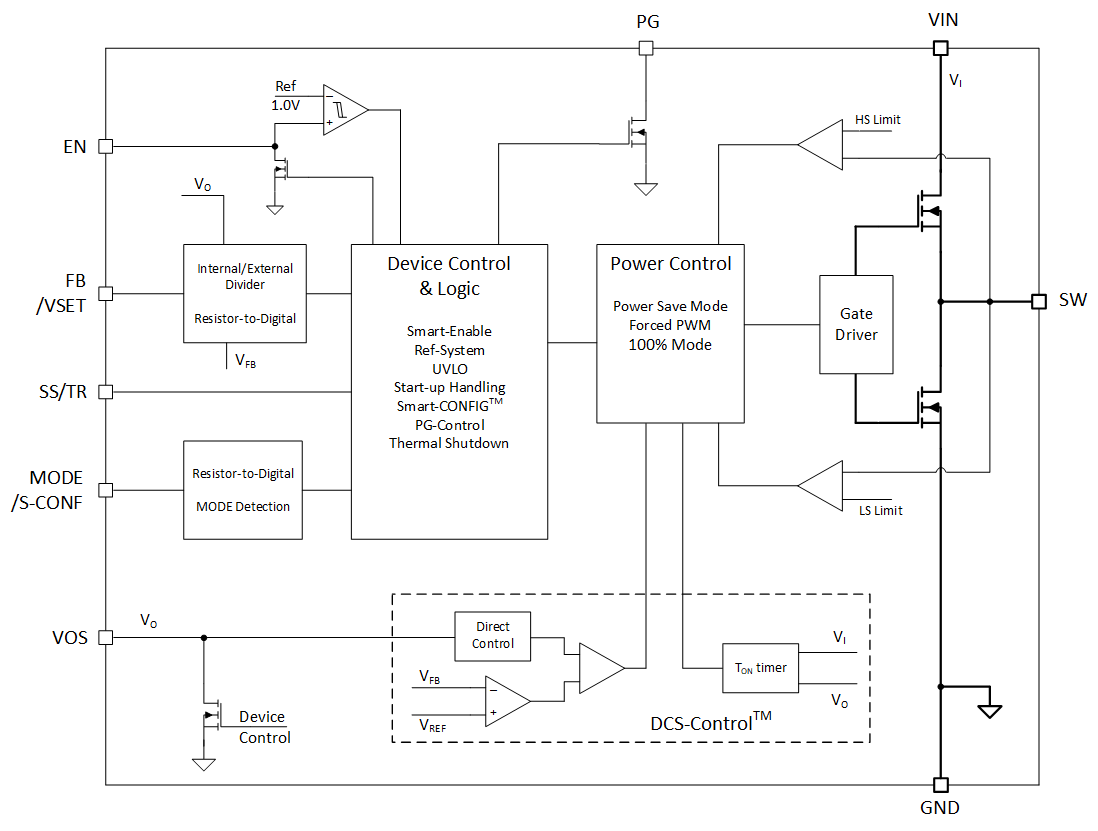
GUID-3B574FA7-F8F8-4C51-ABEC-61624CDB1E1E-low.gif Figure 1-1 Functional Block Diagram

The TPS629xx-Q1 was developed using a quality-managed development process, but was not developed in accordance with the IEC 61508 or ISO 26262 standards.

2 Functional Safety Failure In Time (FIT) Rates

This section provides Functional Safety Failure In Time (FIT) rates for the TPS629xx-Q1 based on two different industry-wide used reliability standards:

  • Table 2-1 provides FIT rates based on IEC TR 62380 / ISO 26262 part 11
  • Table 2-2 provides FIT rates based on the Siemens Norm SN 29500-2

Table 2-1 Component Failure Rates per IEC TR 62380 / ISO 26262 Part 11
FIT IEC TR 62380 / ISO 26262 FIT (Failures Per 109 Hours)
Power Dissipation 0.5 W 1.0 W 1.5 W
Total Component FIT Rate 12 26

59

Die FIT Rate 8 22

55

Package FIT Rate 4 4

4

The failure rate and mission profile information in Table 2-1 comes from the Reliability data handbook IEC TR 62380 / ISO 26262 part 11:

  • Mission Profile: Automotive Control
  • Climate type: World-wide Table 8
  • Package factor (lambda 3): Table 17b
  • Substrate Material: FR4
  • EOS FIT rate assumed: 0 FIT
Table 2-2 Component Failure Rates per Siemens Norm SN 29500-2T

Table

Category

Reference FIT Rate

Reference Virtual Tj

5

CMOS, BICMOS Digital, analog/mixed

25 FIT

55°C

The Reference FIT Rate and Reference Virtual Tj (junction temperature) in Table 2-2 come from the Siemens Norm SN 29500-2 tables 1 through 5. Failure rates under operating conditions are calculated from the reference failure rate and virtual junction temperature using conversion infromation in SN 29500-2 section 4.

3 Pin Failure Mode Analysis (Pin FMA)

This section provides a Failure Mode Analysis (FMA) for the pins of the TPS629xx-Q1. The failure modes covered in this document include the typical pin-by-pin failure scenarios:

  • Pin short-circuited to Ground (see Table 3-2)
  • Pin open-circuited (see Table 3-3)
  • Pin short-circuited to an adjacent pin (see Table 3-4)
  • Pin short-circuited to VIN (see Table 3-5)

Table 3-2 through Table 3-5 also indicate how these pin conditions can affect the device as per the failure effects classification in Table 3-1.

Table 3-1 TI Classification of Failure Effects
ClassFailure Effects
APotential device damage that affects functionality
BNo device damage, but loss of functionality
CNo device damage, but performance degradation
DNo device damage, no impact to functionality or performance

Figure 3-1 shows the TPS629xx-Q1 pin diagram. For a detailed description of the device pins please refer to the 'Pin Configuration and Functions' section in the TPS629xx-Q1 datasheet.


GUID-20210325-CA0I-2MJ3-CCQS-2K6FCVDLHZ9H-low.gif
Figure 3-1 PIin Diagram

Following are the assumptions of use and the device configuration assumed for the pin FMA in this section:

  • The device is operating in one of the two typical application configurations show in Figure 3-2 or Figure 3-3.


Figure 3-2 Adjustable VO Operation Schematic


Figure 3-3 Selectable VO Operation Schematic
Table 3-2 Pin FMA for Device Pins Short-Circuited to Ground
Pin NamePin No.Application ConfigurationDescription of Potential Failure Effect(s)Failure Effect Class
PG

1

Loss of PG functionalityC
SW

2

Possible device damage A
VOS

3

Loss of output voltageB
GND

4

Intended pin connectionD
EN

5

The device does not power on. B
VIN

6

The device does not power on.B
MODE/S-CONF

7

External FB(3)The device runs in 2.5M-Hz APFM with AEE mode.(5)C(5)
Internal FB(4)Loss of output voltage regulation. Output voltage goes to VIN.(5)
Possible device damage. (2) Absolute maximum voltage may be exceeded.
A(5)
SS/TR

8

The device does not power on. B
FB/VSET

9

External FB(3) Loss of output voltage regulation. Output voltage goes to VIN.
Possible device damage. (2)Absolute maximum voltage may be exceeded.
A
Internal FB(4) The device regulates output voltage to 1.2 V. D
Table 3-3 Pin FMA for Device Pins Open-Circuited
Pin NamePin No.Application ConfigurationDescription of Potential Failure Effect(s)Failure Effect Class
PG

1

Loss of PG functionalityC
SW

2

Loss of output voltage regulation B
VOS

3

External FB(3)Open loop operation. Undetermined output voltage behavior

B

Internal FB(4)Loss of output voltage regulation. Output voltage may go to VIN.
Possible device damage. (2) Absolute maximum voltage may be exceeded.
A
GND

4

Potential device damageA
EN

5

The device does not power on.B
VIN

6

The device does not power on. B
MODE/S-CONF

7

External FB(3)The device runs in 2.5-MHz APFM with AEE mode(5). Output voltage is not set based on the external resistor divider ratio. Instead, VOUT is set according to the internal FB (VSET) table based on external feedback resistance values.B(5)
Internal FB(4)The device runs in 2.5-MHz APFM with AEE mode.(5)C(5)
SS/TR

8

Allowable pin condition. Soft-start time is minimized. D
FB/VSET

9

External FB(3) Loss of output voltage regulation. Output voltage may go to VIN.
Possible device damage. (2) Absolute maximum voltage may be exceeded.
A
Internal FB(4) The device regulates output voltage to 3.3 V. D
Table 3-4 Pin FMA for Device Pins Short-Circuited to Adjacent Pin
Pin Name Pin No. Shorted to Application Configuration Description of Potential Failure Effect(s) Failure Effect Class
PG 1 SW Loss of output voltage regulation and possible device damage.(1) Absolute maximum voltage may be exceeded if PG is connected to VOS through a resistor. A
SW 2 VOS Loss of output voltage regulation.
Possible device damage.(1) Absolute maximum voltage may be exceeded.
A
VOS 3 GND Loss of output voltage B
GND 4 EN The device does not power on. B
EN 5 VIN The device cannot be disabled. B
VIN 6 MODE/S_CONF External FB(3) The device runs in 2.5-MHz FPFM mode. C
Internal FB(4) Loss of output voltage regulation. Output voltage goes to VIN.(5)
Possible device damage. (2) Absolute maximum voltage may be exceeded.
A
MODE/S_CONF 7 SS/TR External FB(3) The device operating mode is indeterminate. (5) B(5)
Internal FB(4) Loss of output voltage regulation.
Possible device damage.(1) Absolute maximum voltage may be exceeded.
A
SS/TR 8 FB/VSET Output voltage is regulated below the target value. B
FB/VSET 9 PG Loss of output voltage regulation.
Possible device damage.(1) Absolute maximum voltage may be exceeded if PG is connected to VIN through a resistor.
A
Table 3-5 Pin FMA for Device Pins Short-Circuited to VIN
Pin NamePin No.Application ConfigurationDescription of Potential Failure Effect(s)Failure Effect Class
PG

1

Potential device damage. Absolute maximum current rating for the pin.A
SW

2

Possible device damage. (2) Absolute maximum voltage may be exceeded. A
VOS

3

Possible device damage.(1) Absolute maximum voltage may be exceeded.A
GND

4

The device is not functional.B
EN

5

The device cannot be disabled.B
VIN

6

Intended pin connection D
MODE/S-CONF

7

External FB(3)The device runs in 2.5-MHz FPFM mode. (5)C(5)
Internal FB(4)Loss of output voltage regulation. Output voltage goes to VIN.(5)
Possible device damage. (2) Absolute maximum voltage may be exceeded.
A(5)
SS/TR

8

Potential device damage. Absolute maximum current rating for pin A
FB/VSET

9

Possible device damage.(1) Absolute maximum voltage may be exceeded. A
(1) Damage occurs if VIN is greater than the 6-V absolute maximum rating for the pin.
(2) Damage occurs if VIN is greater than the 6-V absolute maximum rating for the VOS pin.
(3) Applies to a typical application schematic as shown in Figure 3-2
(4) Applies to a typical application schematic as shown in Figure 3-3
(5) Assumes Pin FMA condition occurs prior to device being enabled. If Pin FMA condition occurs after the device is operating, the device continues operating as previously configured.

IMPORTANT NOTICE AND DISCLAIMER

TI PROVIDES TECHNICAL AND RELIABILITY DATA (INCLUDING DATASHEETS), DESIGN RESOURCES (INCLUDING REFERENCE DESIGNS), APPLICATION OR OTHER DESIGN ADVICE, WEB TOOLS, SAFETY INFORMATION, AND OTHER RESOURCES “AS IS” AND WITH ALL FAULTS, AND DISCLAIMS ALL WARRANTIES, EXPRESS AND IMPLIED, INCLUDING WITHOUT LIMITATION ANY IMPLIED WARRANTIES OF MERCHANTABILITY, FITNESS FOR A PARTICULAR PURPOSE OR NON-INFRINGEMENT OF THIRD PARTY INTELLECTUAL PROPERTY RIGHTS.

These resources are intended for skilled developers designing with TI products. You are solely responsible for (1) selecting the appropriate TI products for your application, (2) designing, validating and testing your application, and (3) ensuring your application meets applicable standards, and any other safety, security, or other requirements. These resources are subject to change without notice. TI grants you permission to use these resources only for development of an application that uses the TI products described in the resource. Other reproduction and display of these resources is prohibited. No license is granted to any other TI intellectual property right or to any third party intellectual property right. TI disclaims responsibility for, and you will fully indemnify TI and its representatives against, any claims, damages, costs, losses, and liabilities arising out of your use of these resources.

TI’s products are provided subject to TI’s Terms of Sale (www.ti.com/legal/termsofsale.html) or other applicable terms available either on ti.com or provided in conjunction with such TI products. TI’s provision of these resources does not expand or otherwise alter TI’s applicable warranties or warranty disclaimers for TI products.

Mailing Address: Texas Instruments, Post Office Box 655303, Dallas, Texas 75265 

Copyright © 2022, Texas Instruments Incorporated


Texas Instruments

© Copyright 1995-2025 Texas Instruments Incorporated. All rights reserved.
Submit documentation feedback | IMPORTANT NOTICE | Trademarks | Privacy policy | Cookie policy | Terms of use | Terms of sale