• Menu
  • Product
  • Email
  • PDF
  • Order now
  • TPS7A94EVM-046 Evaluation Module

    • SBVU070B September   2021  – August 2022 TPS7A94


  • CONTENTS
  • SEARCH
  • TPS7A94EVM-046 Evaluation Module
  1.   Abstract
  2.   Trademarks
  3. 1Introduction
    1. 1.1 Before You Begin
  4. 2EVM Setup
    1. 2.1 Inputs/Outputs Connectors and Jumper Descriptions
      1. 2.1.1  J1 – IN
      2. 2.1.2  J2 – OUT
      3. 2.1.3  J3
      4. 2.1.4  TP1 – IN
      5. 2.1.5  TP2 – PG
      6. 2.1.6  TP3 – SNS
      7. 2.1.7  TP4 – PG_FB
      8. 2.1.8  TP5 – OUT
      9. 2.1.9  TP6 – EN
      10. 2.1.10 TP7 – GND
      11. 2.1.11 TP8 – GND
    2. 2.2 Soldering Guidelines
    3. 2.3 Equipment Connections
  5. 3Operation
  6. 4PCB Layout
  7. 5Schematic
  8. 6Bill of Materials
  9. 7Revision History
  10. IMPORTANT NOTICE
search No matches found.
  • Full reading width
    • Full reading width
    • Comfortable reading width
    • Expanded reading width
  • Card for each section
  • Card with all content


USER'S GUIDE

TPS7A94EVM-046 Evaluation Module

1 Abstract

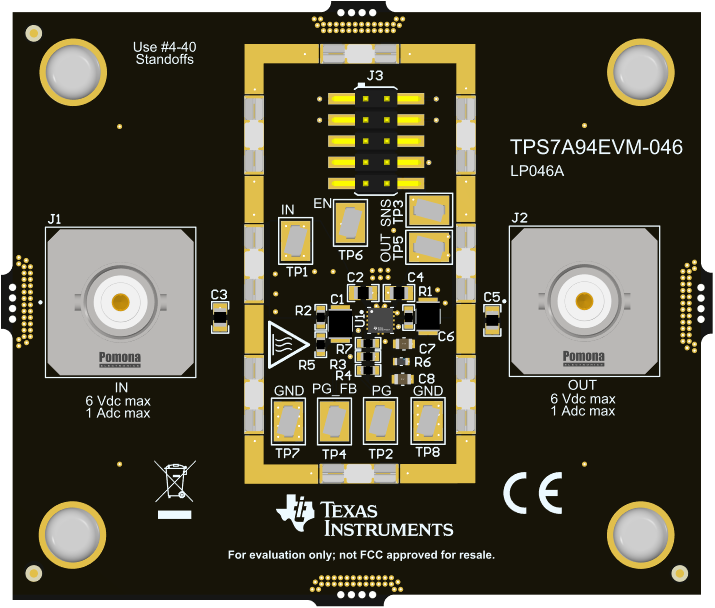
GUID-20210909-SS0I-KD5R-WDJW-QRG9DBXQ3K4S-low.png Figure 1-1 TPS7A94EVM-046 Evaluation Module

This user's guide describes the operational use of the TPS7A94EVM-046 evaluation module (EVM) as a reference design for engineering demonstration and evaluation of the TPS7A9401DSC, an ultra-low noise, ultra-high PSRR, RF low-dropout (LDO) linear regulator. Included in this user's guide are setup and operating instructions, thermal and layout guidelines, a printed circuit board (PCB) layout, a schematic diagram, and a bill of materials (BOM).

Throughout this document the terms demonstration kit, evaluation board, and evaluation module are synonymous with the TPS7A94EVM-046.

Trademarks

All trademarks are the property of their respective owners.

1 Introduction

Texas Instruments' TPS7A94EVM-046 helps design engineers evaluate the operation and performance of the TPS7A94 linear regulator for possible use in their own circuit application. This particular EVM configuration contains a single high-accuracy, small size, adjustable linear regulator for a wide range of applications. The regulator is capable of delivering up to 1 A to the load with low VIN to VOUT dropout voltage. For stability, use a minimum capacitor of 4.7 µF at the input and output.

Table 1-1 lists the related documentation available through the Texas Instrument web site at www.ti.com.

Table 1-1 Related Documentation
Device Literature Number
TPS7A94 https://www.ti.com/lit/pdf/SBVS336


Texas Instruments

© Copyright 1995-2025 Texas Instruments Incorporated. All rights reserved.
Submit documentation feedback | IMPORTANT NOTICE | Trademarks | Privacy policy | Cookie policy | Terms of use | Terms of sale