-
Overvoltage Protection of Resolver-Based Circuits SBOA447 November 2020 ALM2402-Q1 , ALM2402F-Q1 , ALM2403-Q1
Overvoltage Protection of Resolver-Based Circuits
Trademarks
All trademarks are the property of their respective owners.
1 Introduction
To minimize the power dissipation inside an op amp, and thus to improve efficiency of the solution, most of the resolver type of applications are powered from the sub-regulated voltage supply below the battery voltage. For this reason, most high current output amplifiers used in the automotive resolver applications, like ALM2402F-Q1 and ALM2403-Q1, must be fault protected at the PCB level against possible over-voltage (EOS), and or excessive output current, caused by accidental shorting of the amplifier output to the battery or other voltage source beyond the op amp’s power supplies. Since the battery voltage may be higher than the amplifier’s power supply voltage, or even higher than op amp absolute maximum rated voltage, any accidental shorting of the op amp output to the battery may result in damaging the part and thus must be protected.
2 ALM2402F-Q1 Output Fault Protection
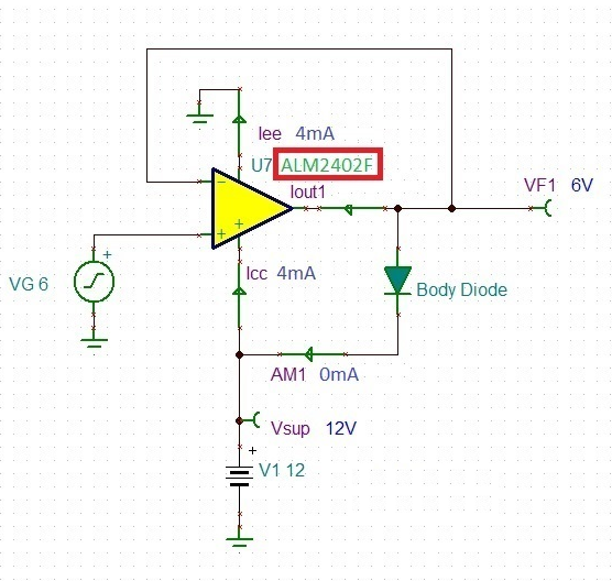
Figure 2-1 shows the ALM2402F-Q1 under normal quiescent condition being powered from 12 V single supply with its input and output voltage at 6 V mid-supply (no fault condition).
 Figure 2-1 ALM2402F-Q1 Normal
Operation
Figure 2-1 ALM2402F-Q1 Normal
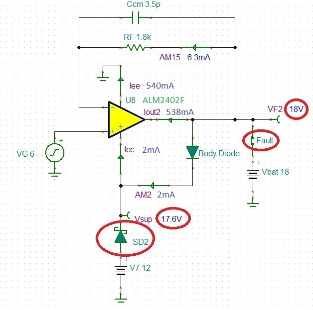
OperationFigure 2-2 shows ALM2402F-Q1 under a fault condition with its output being shorted to an 18 V battery while being powered by a 12 V supply, requiring only protection of a blocking Schottky diode, SD2. Since the absolute maximum rated supply voltage for ALM2402F-Q1 is 18 V, adding the blocking diode, SD2, allows the battery voltage, Vbat, to pull up the amplifier’s positive supply pin, Vsup, to 17.6 V without any damage.
 Figure 2-2 ALM2402F-Q1 18 V Battery Fault
Protection
Figure 2-2 ALM2402F-Q1 18 V Battery Fault
ProtectionThe addition of 1.8kΩ resistor in the feedback, RF, shown in Figure 2-2, limits to 10mA maximum allowable current through the internal back-to-back input protection diodes located between the ALM2402F-Q1 input terminals.
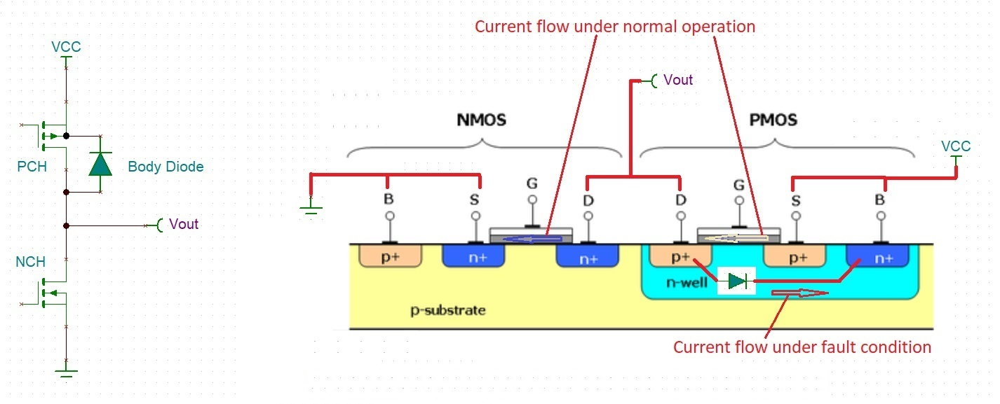
Under the short to battery conditions output of ALM2402F-Q1 sinks 538mA short-circuit current (see Figure 2-2) attempting to bring down the output voltage. At the same time a body diode - an internal drain-to-nwell, p-n junction of P-channel output transistor - supplies 2mA quiescent current to bias the first two internal stages of the amplifier. Under normal operation of the output PMOS transistor, the current flows through the enhanced p-channel from Vcc to Vout. However, under the fault conditions, when Vout is above Vcc, normal operation of PMOS is shut down (Vgs=0) and thus the current flows in a reverse direction from the output, Vout, through drain-to-nwell body diode to a positive supply – see Figure 2-3. For this reason, under fault condition Vsup gets pulled up within a diode drop below Vbat voltage (see Figure 2-2).
 Figure 2-3 Normal vs. Fault Operation of
the Output Stage