-
LM5170-Q1 マルチフェーズ双方向電流コントローラ
- 1 特長
- 2 アプリケーション
- 3 概要
- 4 Revision History
- 5 概要 (続き)
- 6 Pin Configuration and Functions
- 7 Specifications
-
8 Detailed Description
- 8.1 Overview
- 8.2 Functional Block Diagram
- 8.3
Feature Description
- 8.3.1 Bias Supply (VCC, VCCA)
- 8.3.2 Undervoltage Lockout (UVLO) and Master Enable or Disable
- 8.3.3 High Voltage Input (VIN, VINX)
- 8.3.4 Current Sense Amplifier
- 8.3.5 Control Commands
- 8.3.6 Channel Current Monitor (IOUT1, IOUT2)
- 8.3.7 Cycle-by-Cycle Peak Current Limit (IPK)
- 8.3.8 Error Amplifier
- 8.3.9 Ramp Generator
- 8.3.10 Soft Start
- 8.3.11 Gate Drive Outputs, Dead Time Programming and Adaptive Dead Time (HO1, HO2, LO1, LO2, DT)
- 8.3.12 PWM Comparator
- 8.3.13 Oscillator (OSC)
- 8.3.14 Synchronization to an External Clock (SYNCIN, SYNCOUT)
- 8.3.15 Diode Emulation
- 8.3.16 Power MOSFET Failure Detection and Failure Protection (nFAULT, BRKG, BRKS)
- 8.3.17 Overvoltage Protection (OVPA, OVPB)
- 8.4 Device Functional Modes
- 8.5 Programming
-
9 Application and Implementation
- 9.1 Application Information
- 9.2
Typical Application
- 9.2.1
60-A, Dual-Phase, 48-V to 12-V Bidirectional Converter
- 9.2.1.1 Design Requirements
- 9.2.1.2
Detailed Design Procedure
- 9.2.1.2.1 Determining the Duty Cycle
- 9.2.1.2.2 Oscillator Programming
- 9.2.1.2.3 Power Inductor, RMS and Peak Currents
- 9.2.1.2.4 Current Sense (RCS)
- 9.2.1.2.5 Current Setting Limits (ISETA or ISETD)
- 9.2.1.2.6 Peak Current Limit
- 9.2.1.2.7 Power MOSFETS
- 9.2.1.2.8 Bias Supply
- 9.2.1.2.9 Boot Strap
- 9.2.1.2.10 RAMP Generators
- 9.2.1.2.11 OVP
- 9.2.1.2.12 Dead Time
- 9.2.1.2.13 IOUT Monitors
- 9.2.1.2.14 UVLO Pin Usage
- 9.2.1.2.15 VIN Pin Configuration
- 9.2.1.2.16 Loop Compensation
- 9.2.1.2.17 Soft Start
- 9.2.1.2.18 ISET Pins
- 9.2.1.3 Application Curves
- 9.2.1
60-A, Dual-Phase, 48-V to 12-V Bidirectional Converter
- 10Power Supply Recommendations
- 11Layout
- 12Device and Documentation Support
- 13Mechanical, Packaging, and Orderable Information
- 重要なお知らせ
DATA SHEET
LM5170-Q1 マルチフェーズ双方向電流コントローラ
このリソースの元の言語は英語です。 翻訳は概要を便宜的に提供するもので、自動化ツール (機械翻訳) を使用していることがあり、TI では翻訳の正確性および妥当性につきましては一切保証いたしません。 実際の設計などの前には、ti.com で必ず最新の英語版をご参照くださいますようお願いいたします。
1 特長
- 車載アプリケーション用に AEC-Q100 認定取得済み
- デバイス温度グレード 1:-40℃~+125℃の動作時周囲温度範囲
- デバイス HBM ESD 分類レベル 2
- デバイス CDM ESD 分類レベル C4B
- 機能安全対応
- 100V HV ポートおよび 65V LV ポートの最大定格
- 精度 1% の双方向電流レギュレーション
- 精度 1% のチャネル電流監視
- 5A ピークのハーフ・ブリッジ・ゲート・ドライバ
- プログラム可能またはアダプティブなデッドタイム制御
- 発振器の周波数をプログラム可能で、オプションとして外部クロックへの同期も可能
- 独立したチャネル・イネーブル制御入力
- アナログおよびデジタル・チャネルの電流制御入力
- ピーク電流制限をサイクル単位でプログラム可能
- HV および LV ポートの過電圧保護
- ダイオード・エミュレーションにより負の電流を防止
- ソフトスタート・タイマをプログラム可能
- スタートアップ時の MOSFET 障害検出とサーキット・ブレーカ制御
- マルチフェーズ動作の位相を追加または削減
3 概要
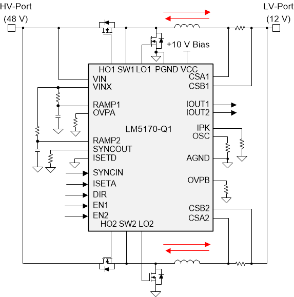
LM5170-Q1 コントローラは、車載用 48V および 12V デュアル・バッテリ・システム用のデュアル・チャネル双方向コンバータに不可欠な高電圧および高精度を実現します。高電圧と低電圧のポート間を流れる平均電流を、DIR 入力信号により指定される方向にレギュレートします。電流のレギュレーション・レベルは、アナログまたはデジタル PWM 入力によりプログラムされます。
デュアル・チャネルの差動電流センシング・アンプと、専用のチャネル電流モニタにより、標準値で 1% の電流精度が得られます。堅牢な 5A のハーフブリッジ・ゲート・ドライバは、並列の MOSFET スイッチを駆動し、チャネルごとに 500W 以上の電力を供給できます。同期整流器のダイオード・エミュレーション・モードにより、負の電流を防止すると同時に、不連続モードの動作が可能になり、軽負荷時に効率を向上できます。多用途な保護機能として、サイクル単位の電流制限、HV と LV の両方のポートにおける過電圧保護、MOSFET 障害検出、過熱保護があります。
製品情報(1)
| 部品番号 | パッケージ | 本体サイズ (公称) |
|---|---|---|
| LM5170-Q1 | TQFP (48) | 7.00mm × 7.00mm |
(1) 提供されているすべてのパッケージについては、巻末の注文情報を参照してください。
 アプリケーションの簡略回路図
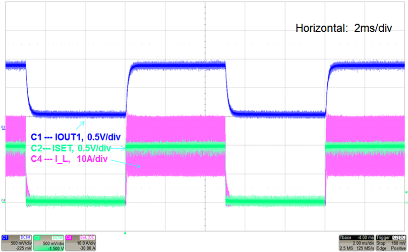
 チャネル電流トラッキングの ISETA コマンド