-
ISO5852S-Q1 分割出力とアクティブ安全機能を搭載した高CMTI2.5Aおよび5A 強化絶縁IGBT、MOSFETゲート・ドライバ
- 1 特長
- 2 アプリケーション
- 3 概要
- 4 改訂履歴
- 5 概要(続き)
- 6 Pin Configuration and Function
-
7 Specifications
- 7.1 Absolute Maximum Ratings
- 7.2 ESD Ratings
- 7.3 Recommended Operating Conditions
- 7.4 Thermal Information
- 7.5 Power Ratings
- 7.6 Insulation Specifications
- 7.7 Safety Limiting Values
- 7.8 Safety-Related Certifications
- 7.9 Electrical Characteristics
- 7.10 Switching Characteristics
- 7.11 Safety and Insulation Characteristics Curves
- 7.12 Typical Characteristics
- 8 Parameter Measurement Information
- 9 Detailed Description
-
10Application and Implementation
- 10.1 Application Information
- 10.2
Typical Applications
- 10.2.1 Design Requirements
- 10.2.2
Detailed Design Procedure
- 10.2.2.1 Recommended ISO5852S-Q1 Application Circuit
- 10.2.2.2 FLT and RDY Pin Circuitry
- 10.2.2.3 Driving the Control Inputs
- 10.2.2.4 Local Shutdown and Reset
- 10.2.2.5 Global-Shutdown and Reset
- 10.2.2.6 Auto-Reset
- 10.2.2.7 DESAT Pin Protection
- 10.2.2.8 DESAT Diode and DESAT Threshold
- 10.2.2.9 Determining the Maximum Available, Dynamic Output Power, POD-max
- 10.2.2.10 Example
- 10.2.2.11 Higher Output Current Using an External Current Buffer
- 10.2.3 Application Curves
- 11Power Supply Recommendations
- 12Layout
- 13デバイスおよびドキュメントのサポート
- 14メカニカル、パッケージ、および注文情報
- 重要なお知らせ
ISO5852S-Q1 分割出力とアクティブ安全機能を搭載した高CMTI2.5Aおよび5A 強化絶縁IGBT、MOSFETゲート・ドライバ
1 特長
- 車載アプリケーションに対応
- 下記内容でAEC-Q100認定済み:
- デバイス温度グレード1: 動作時周囲温度範囲 –40°C~125°C
- デバイスHBM分類レベル3A
- デバイスCDM分類レベルC6
- VCM = 1500Vのとき、最小同相過渡耐性(CMTI) 100kV/μs
- 分割出力により2.5Aのピーク・ソースおよび
5Aのピーク・シンク電流を供給 - 短い伝搬遅延: 76ns (標準値)、
110ns (最大値) - 2Aのアクティブ・ミラー・クランプ
- 出力短絡クランプ
- 短絡時のソフト電源オフ(STO)機能
- 不飽和化検出時のフォルト・アラームはFLTにより通知され、RSTによりリセット
- 入出力低電圧誤動作防止(UVLO)、レディ(RDY)ピンによる標示付き
- 低電源またはフローティング入力時のアクティブ出力プルダウンおよびデフォルトLOW出力
- 入力電源電圧: 2.25V~5.5V
- 出力ドライバ供給電圧: 15V~30V
- CMOS互換の入力
- 20ns未満の入力パルスと過渡ノイズを除去
- 絶縁サージ耐久電圧: 12800VPK
- 安全関連の認定:
- 8000VPK VIOTMおよび2121VPK VIORMの、DIN V VDE V 0884-10 (VDE V 0884-10):2006-12準拠の強化絶縁
- UL1577準拠で5700VRMSにおいて1分間の絶縁
- CSA Component Acceptance Notice 5A、IEC-60950-1、およびIEC 60601-1最終機器標準
- EN 61010-1およびEN 60950-1準拠のTUV認定
- GB4943.1-2011 CQC認定
- UL、VDE、CQC、TUV準拠の認定は完了、CSAは計画中
2 アプリケーション
- 次のような用途の絶縁IGBTおよびMOSFETドライブ
- HEVおよびEVの電源モジュール
- 産業用モータ制御ドライブ
- 産業用電源
- ソーラー・インバータ
- 誘導加熱
3 概要
ISO5852S-Q1デバイスは、IGBTおよびMOSFET用の5.7kVRMS強化絶縁ゲート・ドライバで、分割出力のOUTHとOUTLがあり、2.5Aのソース電流と5Aのシンク電流を供給できます。入力側は、単一の2.25V~5.5V電源で動作します。出力側は、最低15V、最高30Vの電源を供給できます。2つの相補CMOS入力により、ゲート・ドライバの出力状態が制御されます。伝搬時間が76nsと短いため、出力ステージを正確に制御できます。
製品情報(1)
| 型番 | パッケージ | 本体サイズ(公称) |
|---|---|---|
| ISO5852S-Q1 | SOIC (16) | 10.30mm×7.50mm |
- 利用可能なすべてのパッケージについては、このデータシートの末尾にある注文情報を参照してください。
機能ブロック図
4 改訂履歴
| 日付 | 改訂内容 | 注 |
|---|---|---|
| 2016年9月 | * | 初版 |
5 概要(続き)
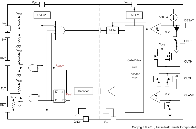
内部不飽和化(DESAT)フォルト検出により、IGBTが過電流状況にあることが認識されます。DESATが検出されると、ミュート・ロジックによりアイソレータの出力がただちにブロックされ、ソフト電源オフ手順が開始されて、OUTHピンがディセーブルされ、OUTLピンが2μsの間LOWになります。OUTLピンが、負の方向に最も大きい供給電圧であるVEE2との比較で2Vに達すると、ゲート・ドライバ出力がVEE2の電位に強制的に設定され、IGBTはただちにオフになります。
不飽和化がアクティブのとき、絶縁バリアを通してフォルト信号が送信され、入力側のFLT出力がLOWになって、アイソレータ入力がブロックされます。ソフト電源オフ期間の間は、ミュート・ロジックがアクティブになります。FLT出力状況はラッチされ、RDYピンがHIGHに移行した後でのみ、RST入力のLOWアクティブ・パルスを使用してリセット可能です。
バイポーラ電源による通常動作時にIGBTがオフになると、出力はVEE2にハード・クランプされます。出力電源がユニポーラの場合、アクティブなミラー・クランプを使用でき、低インピーダンスのパスを通してミラー電流をシンクできるため、高電圧の過渡状況でIGBTが動的にオンになることを防止できます。
ゲート・ドライバの動作準備は、入力側と出力側の電源を監視する2つの低電圧誤動作防止回路により制御されます。いずれかの側の電源が不十分な場合はRDY出力がLOWになり、そうでない場合はこの出力がHIGHになります。
ISO5852S-Q1デバイスは、16ピンのSOICパッケージで供給されます。デバイスの動作は、-40℃~+125℃の周囲温度範囲について規定されています。
6 Pin Configuration and Function
Pin Functions
| PIN | I/O | DESCRIPTION | |
|---|---|---|---|
| NAME | NO. | ||
| CLAMP | 7 | O | Miller clamp output |
| DESAT | 2 | I | Desaturation voltage input |
| FLT | 13 | O | Fault output, active-low during DESAT condition |
| GND1 | 9 | — | Input ground |
| 16 | |||
| GND2 | 3 | — | Gate drive common. Connect to IGBT emitter. |
| IN+ | 10 | I | Non-inverting gate drive voltage control input |
| IN– | 11 | I | Inverting gate drive voltage control input |
| OUTH | 4 | O | Positive gate drive voltage output |
| OUTL | 6 | O | Negative gate drive voltage output |
| RDY | 12 | O | Power-good output, active high when both supplies are good. |
| RST | 14 | I | Reset input, apply a low pulse to reset fault latch. |
| VCC1 | 15 | — | Positive input supply (2.25-V to 5.5-V) |
| VCC2 | 5 | — | Most positive output supply potential. |
| VEE2 | 1 | — | Output negative supply. Connect to GND2 for unipolar supply application. |
| 8 | |||
7 Specifications
7.1 Absolute Maximum Ratings
Over operating free-air temperature range (unless otherwise noted)(1)| MIN | MAX | UNIT | ||||
|---|---|---|---|---|---|---|
| VCC1 | Supply-voltage input side | GND1 – 0.3 | 6 | V | ||
| VCC2 | Positive supply-voltage output side | (VCC2 – GND2) | –0.3 | 35 | V | |
| VEE2 | Negative supply-voltage output side | (VEE2 – GND2) | –17.5 | 0.3 | V | |
| V(SUP2) | Total-supply output voltage | (VCC2 - VEE2) | –0.3 | 35 | V | |
| V(OUTH) | Positive gate-driver output voltage | VEE2 – 0.3 | VCC2 + 0.3 | V | ||
| V(OUTL) | Negative gate-driver output voltage | VEE2 – 0.3 | VCC2 + 0.3 | V | ||
| I(OUTH) | Gate-driver high output current | Maximum pulse width = 10 μs, Maximum duty cycle = 0.2%) | 2.7 | A | ||
| I(OUTL) | Gate-driver low output current | Maximum pulse width = 10 μs, Maximum duty cycle = 0.2%) | 5.5 | A | ||
| V(LIP) | Voltage at IN+, IN–,FLT, RDY, RST | GND1 – 0.3 | VCC1 + 0.3 | V | ||
| I(LOP) | Output current of FLT, RDY | 10 | mA | |||
| V(DESAT) | Voltage at DESAT | GND2 – 0.3 | VCC2 + 0.3 | V | ||
| V(CLAMP) | Clamp voltage | VEE2 – 0.3 | VCC2 + 0.3 | V | ||
| TJ | Junction temperature | –40 | 150 | °C | ||
| TSTG | Storage temperature | –65 | 150 | °C | ||
7.2 ESD Ratings
| VALUE | UNIT | |||
|---|---|---|---|---|
| V(ESD) | Electrostatic discharge | Human-body model (HBM), per AEC Q100-002(1) | ±4000 | V |
| Charged-device model (CDM), per AEC Q100-011 | ±1500 | |||
7.3 Recommended Operating Conditions
over operating free-air temperature range (unless otherwise noted)| MIN | NOM | MAX | UNIT | ||
|---|---|---|---|---|---|
| VCC1 | Supply-voltage input side | 2.25 | 5.5 | V | |
| VCC2 | Positive supply-voltage output side (VCC2 – GND2) | 15 | 30 | V | |
| V(EE2) | Negative supply-voltage output side (VEE2 – GND2) | –15 | 0 | V | |
| V(SUP2) | Total supply-voltage output side (VCC2 – VEE2) | 15 | 30 | V | |
| V(IH) | High-level input voltage (IN+, IN–, RST) | 0.7 × VCC1 | VCC1 | V | |
| V(IL) | Low-level input voltage (IN+, IN–, RST) | 0 | 0.3 × VCC1 | V | |
| tUI | Pulse width at IN+, IN– for full output (CLOAD = 1 nF) | 40 | ns | ||
| tRST | Pulse width at RST for resetting fault latch | 800 | ns | ||
| TA | Ambient temperature | –40 | 125 | °C | |
7.4 Thermal Information
| THERMAL METRIC(1) | ISO5852S-Q1 | UNIT | |
|---|---|---|---|
| DW (SOIC) | |||
| 16 PINS | |||
| RθJA | Junction-to-ambient thermal resistance | 99.6 | °C/W |
| RθJC(top) | Junction-to-case (top) thermal resistance | 48.5 | °C/W |
| RθJB | Junction-to-board thermal resistance | 56.5 | °C/W |
| ψJT | Junction-to-top characterization parameter | 29.2 | °C/W |
| ψJB | Junction-to-board characterization parameter | 56.5 | °C/W |
7.5 Power Ratings
Full-chip power dissipation is derated 10.04 mW/°C beyond 25°C ambient temperature. At 125°C ambient temperature, a maximum of 251 mW total power dissipation is allowed. Power dissipation can be optimized depending on ambient temperature and board design, while ensuring that the junction temperature does not exceed 150°C.| PARAMETER | TEST CONDITIONS | MIN | TYP | MAX | UNIT | |
|---|---|---|---|---|---|---|
| PD | Maximum power dissipation (both sides) | VCC1 = 5.5-V, VCC2 = 30-V, TA = 25°C | 1255 | mW | ||
| PID | Maximum input power dissipation | VCC1 = 5.5-V, VCC2 = 30-V, TA = 25°C | 175 | mW | ||
| POD | Maximum output power dissipation | VCC1 = 5.5-V, VCC2 = 30-V, TA = 25°C | 1080 | mW | ||
7.6 Insulation Specifications
| PARAMETER | TEST CONDITIONS | VALUE | UNIT | |
|---|---|---|---|---|
| GENERAL | ||||
| CLR | External clearance(1) | Shortest terminal-to-terminal distance through air | 8 | mm |
| CPG | External creepage(1) | Shortest terminal-to-terminal distance across the package surface | 8 | mm |
| DTI | Distance through the insulation | Minimum internal gap (internal clearance) | 21 | µm |
| CTI | Comparative tracking index | DIN EN 60112 (VDE 0303-11); IEC 60112; Material Group I according to IEC 60664-1; UL 746A | >600 | V |
| Material group | I | |||
| Overvoltage Category | Rated mains voltage ≤ 600 VRMS | I-IV | ||
| Rated mains voltage ≤ 1000 VRMS | I-III | |||
| DIN V VDE V 0884-10 (VDE V 0884-10):2006-12(2) | ||||
| VIORM | Maximum repetitive peak isolation voltage | AC voltage (bipolar) | 2121 | VPK |
| VIOWM | Maximum isolation working voltage | AC voltage (sine wave) Time dependent dielectric breakdown (TDDB) test, see Figure 1 | 1500 | VRMS |
| DC voltage | 2121 | VDC | ||
| VIOTM | Maximum transient isolation voltage | VTEST = VIOTM; t = 60 s (qualification); t = 1 s (100% production) | 8000 | VPK |
| VIOSM | Maximum surge isolation voltage(3) | Test method per IEC 60065, 1.2/50 µs waveform, VTEST = 1.6 × VIOSM = 12800 VPK (qualification) | 8000 | |
| qpd | Apparent charge(4) | Method a: After I/O safety test subgroup 2/3, Vini = VIOTM, tini = 60 s; Vpd(m) = 1.2 × VIORM = 2545 VPK , tm = 10 s |
≤5 | pC |
| Method a: After environmental tests subgroup 1, Vini = VIOTM, tini = 60 s; Vpd(m) = 1.6 × VIORM = 3394 VPK , tm = 10 s |
≤5 | |||
| Method b1: At routine test (100% production) and preconditioning (type test) Vini = VIOTM, tini = 60 s; Vpd(m) = 1.875× VIORM = 3977 VPK , tm = 10 s |
≤5 | |||
| CIO | Barrier capacitance, input to output(5) | VIO = 0.4 sin (2πft), f = 1 MHz | 1 | pF |
| RIO | Isolation resistance, input to output(5) | VIO = 500 V, TA = 25°C | > 1012 | Ω |
| VIO = 500 V, 100°C ≤ TA ≤ 125°C | > 1011 | |||
| VIO = 500 V at TS = 150°C | > 109 | |||
| Pollution degree | 2 | |||
| Climatic category | ||||
| UL 1577 | ||||
| VISO | Withstand isolation voltage | VTEST = VISO = 5700 VRMS, t = 60 s (qualification); VTEST = 1.2 × VISO = 6840 VRMS, t = 1 s (100% production) | 5700 | VRMS |
7.7 Safety Limiting Values
Safety limiting intends to minimize potential damage to the isolation barrier upon failure of input or output circuitry. A failure of the I/O can allow low resistance to ground or the supply and, without current limiting, dissipate sufficient power to overheat the die and damage the isolation barrier, potentially leading to secondary system failures.| PARAMETER | TEST CONDITIONS | MIN | TYP | MAX | UNIT | |
|---|---|---|---|---|---|---|
| IS | Safety input, output, or supply current | RθJA = 99.6°C/W, VI = 2.75 V, TJ = 150°C, TA = 25°C, see Figure 2 | 456 | mA | ||
| RθJA = 99.6°C/W, VI = 3.6 V, TJ = 150°C, TA = 25°C, see Figure 2 | 346 | |||||
| RθJA = 99.6°C/W, VI = 5.5 V, TJ = 150°C, TA = 25°C, see Figure 2 | 228 | |||||
| RθJA = 99.6°C/W, VI = 15 V, TJ = 150°C, TA = 25°C, see Figure 2 | 84 | |||||
| RθJA = 99.6°C/W, VI = 30 V, TJ = 150°C, TA = 25°C, see Figure 2 | 42 | |||||
| PS | Safety input, output, or total power | RθJA = 99.6°C/W, TJ = 150°C, TA = 25°C, see Figure 3 | 255(1) | mW | ||
| TS | Maximum ambient safety temperature | 150 | °C | |||
The safety-limiting constraint is the maximum junction temperature specified in the data sheet. The power dissipation and junction-to-air thermal impedance of the device installed in the application hardware determines the junction temperature. The assumed junction-to-air thermal resistance in the Thermal Information table is that of a device installed on a high-K test board for leaded surface-mount packages. The power is the recommended maximum input voltage times the current. The junction temperature is then the ambient temperature plus the power times the junction-to-air thermal resistance.
7.8 Safety-Related Certifications
| VDE | CSA | UL | CQC | TUV |
|---|---|---|---|---|
| Certified according to DIN V VDE V 0884-10 (VDE V 0884-10):2006-12 and DIN EN 61010-1 (VDE 0411-1):2011-07 |
Plan to certify under CSA Component Acceptance Notice 5A, IEC 60950-1, and IEC 60601-1 | Recognized under UL 1577 Component Recognition Program | Certified according to GB4943.1-2011 | Certified according to EN 61010-1:2010 (3rd Ed) and EN 60950-1:2006/A11:2009/A1:2010/ A12:2011/A2:2013 |
| Reinforced Insulation Maximum Transient isolation voltage, 8000 VPK; Maximum surge isolation voltage, 8000 VPK, Maximum repetitive peak isolation voltage, 2121 VPK |
Isolation Rating of 5700 VRMS; Reinforced insulation per CSA 60950-1- 07+A1+A2 and IEC 60950-1 (2nd Ed.), 800 VRMS max working voltage (pollution degree 2, material group I) ; 2 MOPP (Means of Patient Protection) per CSA 60601-1:14 and IEC 60601-1 Ed. 3.1, 250 VRMS (354 VPK) max working voltage |
Single Protection, 5700 VRMS (1) | Reinforced Insulation, Altitude ≤ 5000m, Tropical climate, 400 VRMS maximum working voltage | 5700 VRMS Reinforced insulation per EN 61010-1:2010 (3rd Ed) up to working voltage of 600 VRMS 5700 VRMS Reinforced insulation per EN 60950-1:2006/A11:2009/A1:2010/ A12:2011/A2:2013 up to working voltage of 800 VRMS |
| Certification completed Certificate number: 40040142 |
Certificate planned | Certification completed File number: E181974 |
Certification completed Certificate number: CQC16001141761 |
Certification completed Client ID number: 77311 |
7.9 Electrical Characteristics
Over recommended operating conditions unless otherwise noted. All typical values are at TA = 25°C, VCC1 = 5 V,VCC2 – GND2 = 15 V, GND2 – VEE2 = 8 V
| PARAMETER | TEST CONDITIONS | MIN | TYP | MAX | UNIT | ||
|---|---|---|---|---|---|---|---|
| VOLTAGE SUPPLY | |||||||
| VIT+(UVLO1) | Positive-going UVLO1 threshold-voltage input side (VCC1 – GND1) | 2.25 | V | ||||
| VIT-(UVLO1) | Negative-going UVLO1 threshold-voltage input side (VCC1 – GND1) | 1.7 | V | ||||
| VHYS(UVLO1) | UVLO1 Hysteresis voltage (VIT+ – VIT–) input side | 0.2 | V | ||||
| VIT+(UVLO2) | Positive-going UVLO2 threshold-voltage output side (VCC2 – GND2) | 12 | 13 | V | |||
| VIT–(UVLO2) | Negative-going UVLO2 threshold-voltage output side (VCC2 – GND2) | 9.5 | 11 | V | |||
| VHYS(UVLO2) | UVLO2 hysteresis voltage (VIT+ – VIT–) output side | 1 | V | ||||
| IQ1 | Input-supply quiescent current | 2.8 | 4.5 | mA | |||
| IQ2 | Output-supply quiescent current | 3.6 | 6 | mA | |||
| LOGIC I/O | |||||||
| VIT+(IN,RST) | Positive-going input-threshold voltage (IN+, IN–, RST) | 0.7 × VCC1 | V | ||||
| VIT–(IN,RST) | Negative-going input-threshold voltage (IN+, IN–, RST) | 0.3 × VCC1 | V | ||||
| VHYS(IN,RST) | Input hysteresis voltage (IN+, IN–, RST) | 0.15 × VCC1 | V | ||||
| IIH | High-level input leakage at (IN+)(1) | IN+ = VCC1 | 100 | µA | |||
| IIL | Low-level input leakage at (IN–, RST)(2) | IN– = GND1, RST = GND1 | -100 | µA | |||
| IPU | Pullup current of FLT, RDY | V(RDY) = GND1, V(FLT) = GND1 | 100 | µA | |||
| V(OL) | Low-level output voltage at FLT, RDY | I(FLT) = 5 mA | 0.2 | V | |||
| GATE DRIVER STAGE | |||||||
| V(OUTPD) | Active output pulldown voltage | I(OUTH/L) = 200 mA, VCC2 = open | 2 | V | |||
| VOUTH | High-level output voltage | I(OUTH) = –20 mA | VCC2 – 0.5 | VCC2 – 0.24 | V | ||
| VOUTL | Low-level output voltage | I(OUTL) = 20 mA | VEE2 + 13 | VEE2 + 50 | mV | ||
| I(OUTH) | High-level output peak current | IN+ = high, IN– = low, V(OUTH) = VCC2 - 15 V |
1.5 | 2.5 | A | ||
| I(OUTL) | Low-level output peak current | IN+ = low, IN– = high, V(OUTL) = VEE2 + 15 V |
3.4 | 5 | A | ||
| I(OLF) | Low-level output current during fault condition | 130 | mA | ||||
| ACTIVE MILLER CLAMP | |||||||
| V(CLP) | Low-level clamp voltage | I(CLP) = 20 mA | VEE2 + 0.015 | VEE2 + 0.08 | V | ||
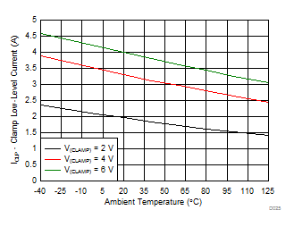
| I(CLP) | Low-level clamp current | V(CLAMP) = VEE2 + 2.5 V | 1.6 | 2.5 | 3.3 | A | |
| V(CLTH) | Clamp threshold voltage | 1.6 | 2.1 | 2.5 | V | ||
| SHORT CIRCUIT CLAMPING | |||||||
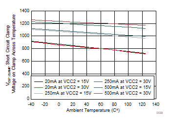
| V(CLP-OUTH) | Clamping voltage (VOUTH – VCC2) |
IN+ = high, IN– = low, tCLP = 10 µs, I(OUTH) = 500 mA | 1.1 | 1.3 | V | ||
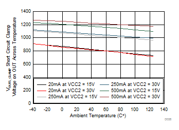
| V(CLP-OUTL) | Clamping voltage (VOUTL – VCC2) |
IN+ = high, IN– = low, tCLP = 10 µs, I(OUTL) = 500 mA | 1.3 | 1.5 | V | ||
| V(CLP-CLP) | Clamping voltage (VCLP – VCC2) |
IN+ = high, IN– = low, tCLP = 10 µs, I(CLP) = 500 mA | 1.3 | V | |||
| V(CLP-CLAMP) | Clamping voltage at CLAMP | IN+ = High, IN– = Low, I(CLP) = 20 mA | 0.7 | 1.1 | V | ||
| V(CLP-OUTL) | Clamping voltage at OUTL (VCLP – VCC2) |
IN+ = High, IN– = Low, I(OUTL) = 20 mA | 0.7 | 1.1 | V | ||
| DESAT PROTECTION | |||||||
| I(CHG) | Blanking-capacitor charge current | V(DESAT) – GND2 = 2 V | 0.42 | 0.5 | 0.58 | mA | |
| I(DCHG) | Blanking-capacitor discharge current | V(DESAT) – GND2 = 6 V | 9 | 14 | mA | ||
| V(DSTH) | DESAT threshold voltage with respect to GND2 | 8.3 | 9 | 9.5 | V | ||
| V(DSL) | DESAT voltage with respect to GND2, when OUTH or OUTL is driven low | 0.4 | 1 | V | |||
7.10 Switching Characteristics
Over recommended operating conditions unless otherwise noted. All typical values are at TA = 25°C, VCC1 = 5 V,VCC2 – GND2 = 15 V, GND2 – VEE2 = 8 V
| PARAMETER | TEST CONDITIONS | MIN | TYP | MAX | UNIT | ||
|---|---|---|---|---|---|---|---|
| tr | Output-signal rise time at OUTH | CLOAD = 1 nF | See Figure 44, Figure 45, and Figure 46 | 12 | 18 | 35 | ns |
| tf | Output-signal fall time at OUTL | CLOAD = 1 nF | 12 | 20 | 37 | ns | |
| tPLH, tPHL | Propagation Delay | CLOAD = 1 nF | 76 | 110 | ns | ||
| tsk-p | Pulse skew |tPHL – tPLH| | CLOAD = 1 nF | 20 | ns | |||
| tsk-pp | Part-to-part skew | CLOAD = 1 nF | 30(1) | ns | |||
| tGF (IN,/RST) | Glitch filter on IN+, IN–, RST | CLOAD = 1 nF | 20 | 30 | 40 | ns | |
| tDS (90%) | DESAT sense to 90% VOUTH/L delay | CLOAD = 10 nF | 553 | 760 | ns | ||
| tDS (10%) | DESAT sense to 10% VOUTH/L delay | CLOAD = 10 nF | 2 | 3.5 | μs | ||
| tDS (GF) | DESAT-glitch filter delay | CLOAD = 1 nF | 330 | ns | |||
| tDS (FLT) | DESAT sense to FLT-low delay | See Figure 46 | 1.4 | μs | |||
| tLEB | Leading-edge blanking time | See Figure 44 and Figure 45 | 310 | 400 | 480 | ns | |
| tGF(RSTFLT) | Glitch filter on RST for resetting FLT | 300 | 800 | ns | |||
| CI | Input capacitance(2) | VI = VCC1 / 2 + 0.4 × sin (2πft), f = 1 MHz, VCC1 = 5 V | 2 | pF | |||
| CMTI | Common-mode transient immunity | VCM = 1500 V, see Figure 47 | 100 | 120 | kV/μs | ||
7.11 Safety and Insulation Characteristics Curves
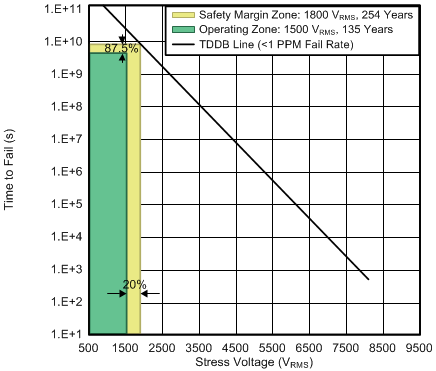
| TA upto 150°C | Stress-voltage frequency = 60 Hz | |||
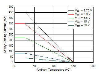 Figure 2. Thermal Derating Curve for Safety Limiting Current per VDE
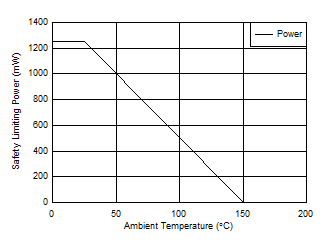 Figure 3. Thermal Derating Curve for Safety Limiting Power per VDE
7.12 Typical Characteristics
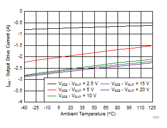
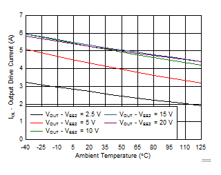
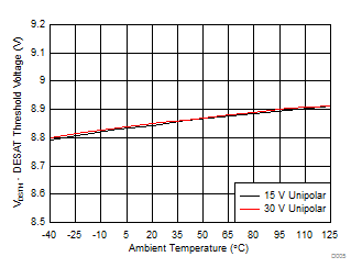
| Unipolar: VCC2 – VEE2 = VCC2 – GND2 |
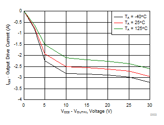
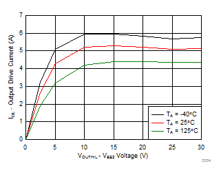
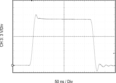
| CL = 1 nF | RGH = 0 Ω | RGL = 0 Ω |
| VCC2 – VEE2 = VCC2 – GND2 = 20 V | ||
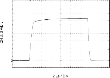
| CL = 100 nF | RGH = 0 Ω | RGL = 0 Ω |
| VCC2 – VEE2 = VCC2 – GND2 = 20 V | ||
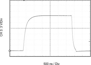
| CL = 10 nF | RGH = 10 Ω | RGL = 5 Ω |
| VCC2 – VEE2 = VCC2 – GND2 = 20 V | ||
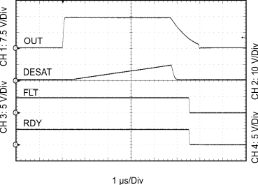
| CL = 10 nF | RGH = 0 Ω | RGL = 0 Ω |
| VCC2 – VEE2 = VCC2 – GND2 = 15 V | DESAT = 220 pF | |
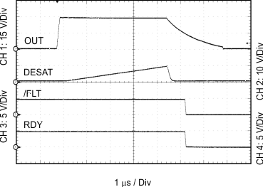
| CL = 10 nF | RGH = 0 Ω | RGL = 0 Ω |
| VCC2 – VEE2 = VCC2 – GND2 = 30 V | DESAT = 220 pF | |

| IN+ = High | IN– = Low |
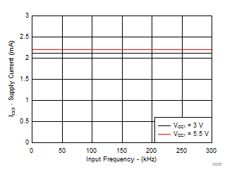
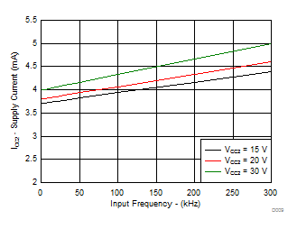
| No CL |
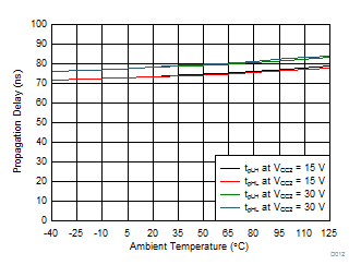
| CL = 1 nF | RGH = 0 Ω | RGL = 0 Ω |
| VCC1 = 5 V |

| RGH = 10 Ω | RGL = 5 Ω | VCC1 = 5 V |
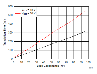
| RGH = 0 Ω | RGL = 0 Ω | VCC1 = 5 V |

| RGH = 10 Ω | RGL = 5 Ω | VCC1 = 5 V |
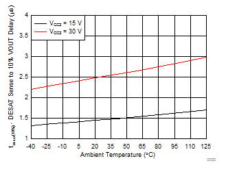
| CL = 10 nF | RGH = 0 Ω | RGL = 0 Ω |
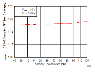
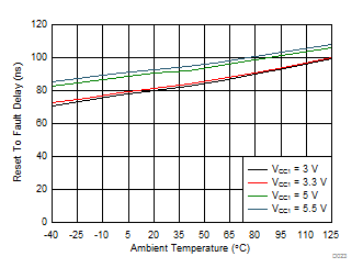
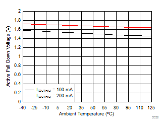
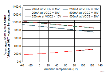
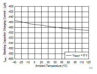
| VCC2 = 15 V | DESAT = 6 V |
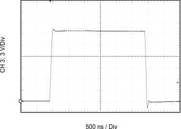
| CL = 10 nF | RGH = 0 Ω | RGL = 0 Ω |
| VCC2 – VEE2 = VCC2 – GND2 = 20 V | ||
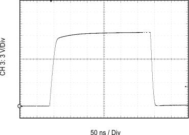
| CL = 1 nF | RGH = 10 Ω | RGL = 5 Ω |
| VCC2 – VEE2 = VCC2 – GND2 = 20 V | ||

| CL = 100 nF | RGH = 10 Ω | RGL = 5 Ω |
| VCC2 – VEE2 = VCC2 – GND2 = 20 V | ||
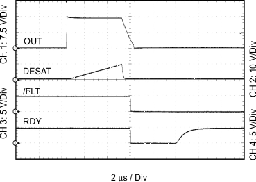
| CL = 10 nF | RGH = 0 Ω | RGL = 0 Ω |
| VCC2 – VEE2 = VCC2 – GND2 = 15 V | DESAT = 220 pF | |
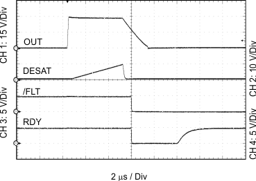
| CL = 10 nF | RGH = 0 Ω | RGL = 0 Ω |
| VCC2 – VEE2 = VCC2 – GND2 = 30 V | DESAT = 220 pF | |
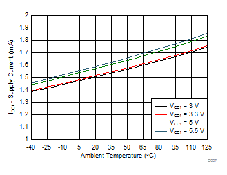
| IN+ = Low | IN– = Low |

| Input frequency = 1 kHz |

| RGH = 10 Ω | RGL = 5 Ω, 20 kHz |
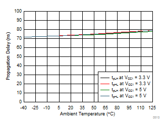
| CL = 1 nF | RGH = 0 Ω | RGL = 0 Ω |
| VCC2 = 15 V |
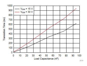
| RGH = 0 Ω | RGL = 0 Ω | VCC1 = 5 V |
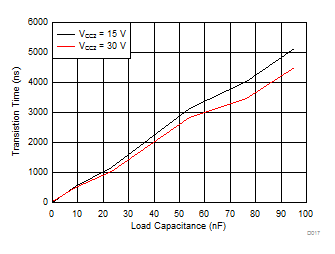
| RGH = 10 Ω | RGL = 5 Ω | VCC1 = 5 V |
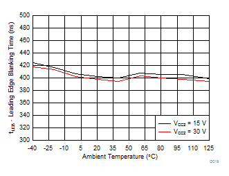
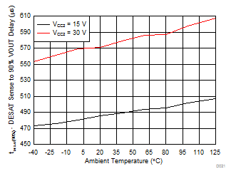
| CL = 10 nF | RGH = 0 Ω | RGL = 0 Ω |

