-
TPA2012D2 2.1W/チャネル、ステレオ、フィルタフリー、Class-Dオーディオ・パワー・アンプ
- 1 特長
- 2 アプリケーション
- 3 概要
- 4 改訂履歴
- 5 Device Comparison Table
- 6 Pin Configuration and Functions
- 7 Specifications
- 8 Parameter Measurement Information
- 9 Detailed Description
- 10Application and Implementation
- 11Power Supply Recommendations
- 12Layout
- 13デバイスおよびドキュメントのサポート
- 14メカニカル、パッケージ、および注文情報
- 重要なお知らせ
DATA SHEET
TPA2012D2 2.1W/チャネル、ステレオ、フィルタフリー、Class-Dオーディオ・パワー・アンプ
このリソースの元の言語は英語です。 翻訳は概要を便宜的に提供するもので、自動化ツール (機械翻訳) を使用していることがあり、TI では翻訳の正確性および妥当性につきましては一切保証いたしません。 実際の設計などの前には、ti.com で必ず最新の英語版をご参照くださいますようお願いいたします。
1 特長
- パッケージ毎の出力電力
- WQFN:
- 2.1W/Ch: 4Ω、5V
- 1.4W/Ch: 8Ω、5V
- 720mW/Ch: 8Ω、3.6V
- DSBGA:
- 1.2W/Ch: 4Ω、5V
(熱により制限あり) - 1.3W/Ch: 8Ω、5V
- 720mW/Ch: 8Ω、3.6V
- 1.2W/Ch: 4Ω、5V
- WQFN:
- 必要な外部部品が2個のみ
- 電源電圧範囲: 2.5V~5.5V
- チャネル別のシャットダウン制御
- 選択可能なゲイン: 6、12、18、24dB
- シャットダウン・ピンの内部プルダウン抵抗
- 高PSRR: 77dB (217Hz時)
- 短いスタートアップ時間(3.5ms)
- 低消費電流
- 低シャットダウン電流
- 短絡保護と熱保護
- 省スペースのパッケージ
- 2.01mm×2.01mm NanoFree™DSBGA (YZH)
- 4mm×4mm Thin QFN (RTJ)、 PowerPAD™
2 アプリケーション
- ワイヤレスまたは携帯電話ハンドセットおよびPDA
- 携帯DVDプレーヤー
- ノートPC
- 携帯ラジオ
- 携帯ゲーム機
- 教育玩具
- USBスピーカー
3 概要
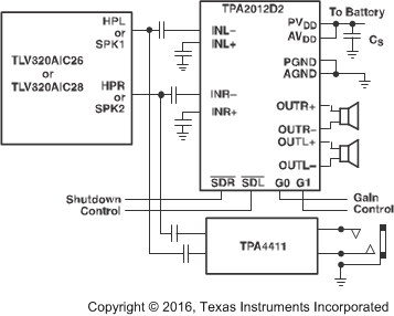
TPA2012D2はステレオ、フィルタフリーのClass-Dオーディオ・アンプで、DSBGAまたはWQFNパッケージで供給されます。TPA2012D2の動作に必要な外付け部品は2個だけです。
TPA2012D2は、チャネル別に独立のシャットダウン制御が可能です。G0、G1ゲイン選択ピンの設定により、6、12、18、24dBのゲインを選択できます。さらに、高PSRRおよび差動アーキテクチャにより、ノイズ耐性とRF整流が強化されています。これらの特長に加え、起動時間が短く、小型パッケージのTPA2012D2 Class-Dアンプは、携帯電話とPDAのどちらにも理想的な選択肢です。
TPA2012D2は、8Ωの負荷で1.4W/Ch (5V)または
720mW/Ch (3.6V)を駆動できます。TPA2012D2は4Ω負荷も駆動可能です。DSBGAのTPA2012D2は熱的な制限があり、4Ωで2.1W/Chを実現できない可能性があります。
DSBGAでの最大出力電力は、基板の放熱能力によって決まります。DSBGAで、WQFNパッケージに関連して熱的に制限されている領域を図33に示します。TPA2012D2は、過熱保護と短絡保護の機能を備えています。
製品情報(1)
| 型番 | パッケージ | 本体サイズ(公称) |
|---|---|---|
| TPA2012D2 | DSBGA (16) | 2.01mm×2.01mm |
| WQFN (20) | 4.00mm×4.00mm |
- 提供されているすべてのパッケージについては、巻末の注文情報を参照してください。
簡略化されたアプリケーション回路図
4 改訂履歴
Changes from E Revision (September 2016) to F Revision
- 「製品情報」表内の本体サイズの値を変更: DSBGAは4.00 mm×4.00mmから2.01mm×2.01mmへ、WQFNは2.01mm×2.01mmから4.00mm×4.00mmへGo
Changes from D Revision (June 2008) to E Revision
- Added 「ESD定格」表、「機能説明」セクション、「デバイスの機能モード」セクション、「アプリケーションと実装」セクション、「電源に関する推奨事項」セクション、「レイアウト」セクション、「デバイスおよびドキュメントのサポート」セクション、「メカニカル、パッケージ、および注文情報」セクションGo
- Deleted データシートの末尾にあるPOAを参照し、利用可能なオプションの表をGo
- Deleted previous application schematics: Typical Application Circuit (previously Figure 33), TPA2012D2 Application Schematic With Differential Input and Input Capacitors (previously Figure 34), and TPA2012D2 Application Schematic With Single-Ended Input (previously Figure 35)Go
5 Device Comparison Table
| DEVICE NO. | SPEAKER AMP TYPE | SPECIAL FEATURE | OUTPUT POWER (M) | PSRR (dB) |
|---|---|---|---|---|
| TPA2012D2 | Class D | — | 2.1 | 71 |
| TPA2016D2 | Class D | AGC/DRC | 2.8 | 80 |
| TPA2026D2 | Class D | AGC/DRC | 3.2 | 80 |
6 Pin Configuration and Functions
YZH Package
16-Pin DSBGA
Top View
RTJ Package
20-Pin WQFN
Top View
Pin Functions
| PIN | I/O | DESCRIPTION | ||
|---|---|---|---|---|
| NAME | DSBGA | WQFN | ||
| AGND | C3 | 18 | I | Analog ground |
| AVDD | D2 | 9 | I | Analog supply (must be same voltage as PVDD) |
| G0 | C2 | 15 | I | Gain select (LSB) |
| G1 | B2 | 1 | I | Gain select (MSB) |
| INL– | B1 | 19 | I | Left channel negative input |
| INL+ | A1 | 20 | I | Left channel positive input |
| INR– | C1 | 17 | I | Right channel negative input |
| INR+ | D1 | 16 | I | Right channel positive input |
| NC | — | 6, 10 | — | No internal connection |
| OUTL– | A4 | 5 | O | Left channel negative differential output |
| OUTL+ | A3 | 2 | O | Left channel positive differential output |
| OUTR– | D4 | 11 | O | Right channel negative differential output |
| OUTR+ | D3 | 14 | O | Right channel positive differential output |
| PGND | C4 | 4, 12 | I | Power ground |
| PVDD | A2 | 3, 13 | I | Power supply (must be same voltage as AVDD) |
| SDL | B4 | 7 | I | Left channel shutdown terminal (active low) |
| SDR | B3 | 8 | I | Right channel shutdown terminal (active low) |
| Thermal Pad | — | — | — | Connect the thermal pad of WQFN package to PCB GND |
7 Specifications
7.1 Absolute Maximum Ratings
over operating free-air temperature range (unless otherwise noted)(1)| MIN | MAX | UNIT | ||
|---|---|---|---|---|
| Supply voltage, VSS (AVDD, PVDD) | Active mode | –0.3 | 6 | V |
| Shutdown mode | –0.3 | 7 | ||
| Input voltage, VI | –0.3 | VDD + 0.3 | V | |
| Continuous total power dissipation | See Dissipation Rating Table | |||
| Operating junction temperature, TJ | –40 | 150 | °C | |
| Storage temperature, Tstg | –65 | 150 | °C | |
(1) Stresses beyond those listed under Absolute Maximum Ratings may cause permanent damage to the device. These are stress ratings only, which do not imply functional operation of the device at these or any other conditions beyond those indicated under Recommended Operating Conditions. Exposure to absolute-maximum-rated conditions for extended periods may affect device reliability.
7.2 ESD Ratings
| VALUE | UNIT | |||
|---|---|---|---|---|
| V(ESD) | Electrostatic discharge | Human-body model (HBM), per ANSI/ESDA/JEDEC JS-001(1) | ±2000 | V |
| Charged-device model (CDM), per JEDEC specification JESD22-C101(2) | ±1500 | |||
(1) JEDEC document JEP155 states that 500-V HBM allows safe manufacturing with a standard ESD control process.
(2) JEDEC document JEP157 states that 250-V CDM allows safe manufacturing with a standard ESD control process.
7.3 Recommended Operating Conditions
over operating free-air temperature range (unless otherwise noted)| MIN | MAX | UNIT | ||
|---|---|---|---|---|
| VSS | Supply voltage, AVDD, PVDD | 2.5 | 5.5 | V |
| VIH | High-level input voltage, SDL, SDR, G0, G1 | 1.3 | V | |
| VIL | Low-level input voltage, SDL, SDR, G0, G1 | 0.35 | V | |
| TA | Operating free-air temperature | –40 | 85 | °C |
7.4 Thermal Information
| THERMAL METRIC(1) | TPA2012D2 | UNIT | ||
|---|---|---|---|---|
| YZH (DSBGA) | RTJ (WQFN) | |||
| 16 PINS | 20 PINS | |||
| RθJA | Junction-to-ambient thermal resistance | 71.4 | 34.6 | °C/W |
| RθJC(top) | Junction-to-case (top) thermal resistance | 0.4 | 34.3 | °C/W |
| RθJB | Junction-to-board thermal resistance | 14 | 11.5 | °C/W |
| ψJT | Junction-to-top characterization parameter | 1.8 | 0.4 | °C/W |
| ψJB | Junction-to-board characterization parameter | 13.3 | 11.6 | °C/W |
| RθJC(bot) | Junction-to-case (bottom) thermal resistance | — | 3.2 | °C/W |
(1) For more information about traditional and new thermal metrics, see the Semiconductor and IC Package Thermal Metrics application report.
7.5 Electrical Characteristics
TA = 25°C (unless otherwise noted)| PARAMETER | TEST CONDITIONS | MIN | TYP | MAX | UNIT | ||
|---|---|---|---|---|---|---|---|
| |VOO| | Output offset voltage (measured differentially) | Inputs ac grounded, AV = 6 dB, VDD = 2.5 to 5.5 V | 5 | 25 | mV | ||
| PSRR | Power supply rejection ratio | VDD = 2.5 to 5.5 V | –75 | –55 | dB | ||
| Vicm | Common-mode input voltage | 0.5 | VDD – 0.8 | V | |||
| CMRR | Common-mode rejection ration | Inputs shorted together, VDD = 2.5 to 5.5 V | –69 | –50 | dB | ||
| |IIH| | High-level input current | VDD = 5.5 V, VI = VDD | 50 | µA | |||
| |IIL| | Low-level input current | VDD = 5.5 V, VI = 0 V | 5 | µA | |||
| IDD | Supply current | VDD = 5.5 V, no load or output filter | 6 | 9 | mA | ||
| VDD = 3.6 V, no load or output filter | 5 | 7.5 | |||||
| VDD = 2.5 V, no load or output filter | 4 | 6 | |||||
| Shutdown mode | 1.5 | µA | |||||
| rDS(on) | Static drain-source on-state resistance | VDD = 5.5 V | 500 | mΩ | |||
| VDD = 3.6 V | 570 | ||||||
| VDD = 2.5 V | 700 | ||||||
| Output impedance in shutdown mode | V(SDR, SDL)= 0.35 V | 2 | kΩ | ||||
| f(sw) | Switching frequency | VDD = 2.5 V to 5.5 V | 250 | 300 | 350 | kHz | |
| Closed-loop voltage gain | G0, G1 = 0.35 V | 5.5 | 6 | 6.5 | dB | ||
| G0 = VDD, G1 = 0.35 V | 11.5 | 12 | 12.5 | ||||
| G0 = 0.35 V, G1 = VDD | 17.5 | 18 | 18.5 | ||||
| G0, G1 = VDD | 23.5 | 24 | 24.5 | ||||
| OPERATING CHARACTERISTICS, RL = 8 Ω | |||||||
| PO | Output power (per channel) | RL = 8 Ω | VDD = 5 V, f = 1 kHz, THD = 10% |
1.4 | W | ||
| VDD = 3.6 V, f = 1 kHz, THD = 10% |
0.72 | ||||||
| RL = 4 Ω | VDD = 5 V, f = 1 kHz, THD = 10% |
2.1 | |||||
| THD+N | Total harmonic distortion plus noise | PO = 1 W, VDD = 5 V, AV = 6 dB, f = 1 kHz | 0.14% | ||||
| PO = 0.5 W, VDD = 5 V, AV = 6 dB, f = 1 kHz | 0.11% | ||||||
| Channel crosstalk | f = 1 kHz | –85 | dB | ||||
| kSVR | Supply ripple rejection ratio | VDD = 5 V, AV = 6 dB, f = 217 Hz | –77 | dB | |||
| VDD = 3.6 V, AV = 6 dB, f = 217 Hz | –73 | ||||||
| CMRR | Common mode rejection ratio | VDD = 3.6 V, VIC = 1 Vpp, f = 217 Hz | –69 | dB | |||
| Input impedance | Av = 6 dB | 28.1 | kΩ | ||||
| Av = 12 dB | 17.3 | ||||||
| Av = 18 dB | 9.8 | ||||||
| Av = 24 dB | 5.2 | ||||||
| Start-up time from shutdown | VDD = 3.6 V | 3.5 | ms | ||||
| Vn | Output voltage noise | VDD = 3.6 V, f = 20 to 20 kHz, inputs are ac grounded, AV = 6 dB |
No weighting | 35 | µV | ||
| A weighting | 27 | ||||||
7.6 Dissipation Rating Table
| PACKAGE | TA = 25°C POWER RATING(1) |
DERATING FACTOR |
TA = 75°C POWER RATING |
TA = 85°C POWER RATING |
|---|---|---|---|---|
| RTJ | 5.2 W | 41.6 mW/°C | 3.12 W | 2.7 W |
| YZH | 1.2 W | 9.12 mW/°C | 690 mW | 600 mW |
(1) This data was taken using 2-oz trace and copper pad that is soldered directly to a JEDEC standard 4-layer 3 in × 3 in PCB.
7.7 Typical Characteristics
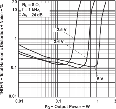 Figure 1. Total Harmonic Distortion
vs Output Power
 Figure 3. Total Harmonic Distortion
vs Output Power
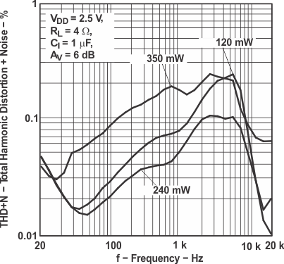 Figure 5. Total Harmonic Distortion vs Frequency
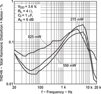 Figure 7. Total Harmonic Distortion vs Frequency
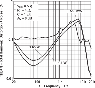 Figure 9. Total Harmonic Distortion vs Frequency
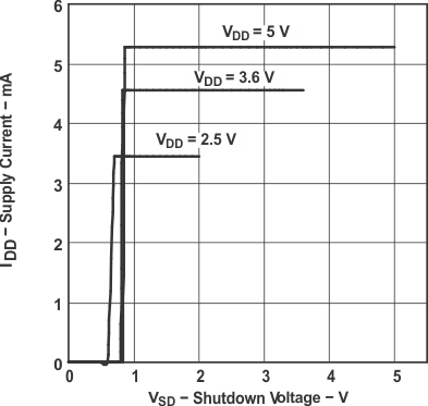 Figure 11. Supply Current vs Shutdown Voltage
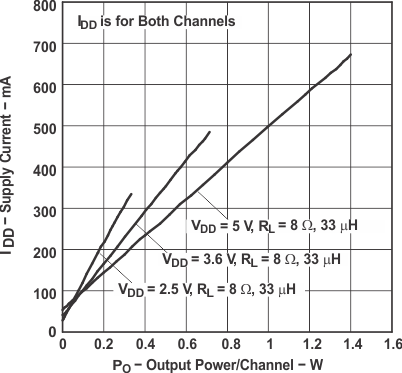 Figure 13. Supply Current vs Output Power
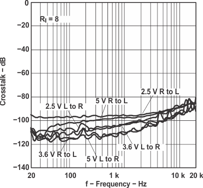 Figure 15. Crosstalk vs Frequency
 Figure 17. Power Supply Rejection Ratio
vs Frequency
 Figure 19. Common-Mode Rejection Ratio
vs Common-Mode Input Voltage
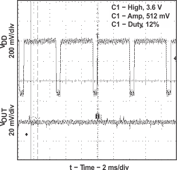 Figure 21. GSM Power Supply Rejection vs Time
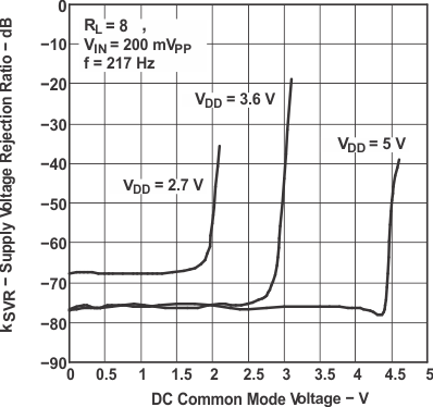 Figure 23. Supply Voltage Rejection Ratio
vs DC Common-Mode Voltage
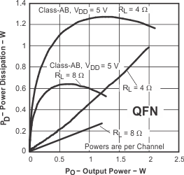 Figure 25. Power Dissipation vs Output Power
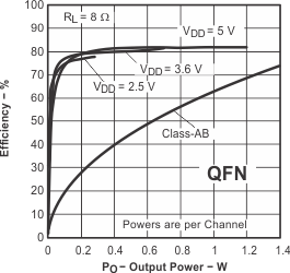 Figure 27. Efficiency vs Output Power
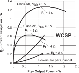 Figure 29. Power Dissipation vs Output Power
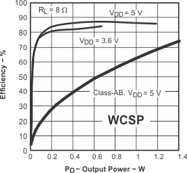 Figure 31. Efficiency vs Output Power
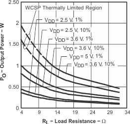 Figure 33. Output Power vs Load Resistance
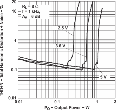 Figure 2. Total Harmonic Distortion
vs Output Power
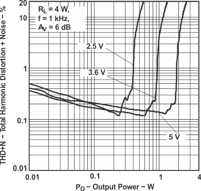 Figure 4. Total Harmonic Distortion
vs Output Power
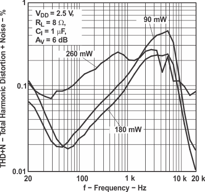 Figure 6. Total Harmonic Distortion vs Frequency
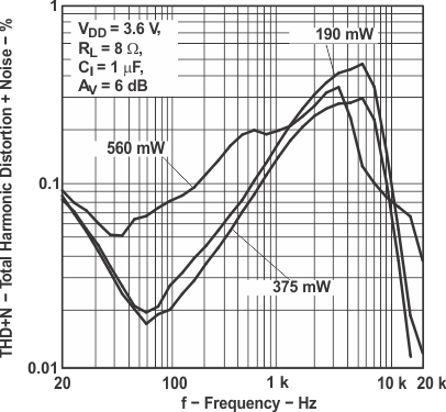 Figure 8. Total Harmonic Distortion vs Frequency
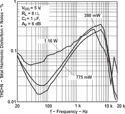 Figure 10. Total Harmonic Distortion vs Frequency
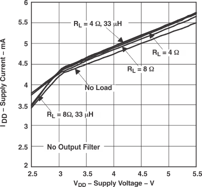 Figure 12. Supply Current vs Supply Voltage
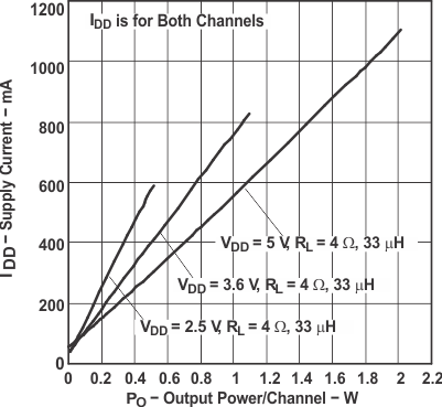 Figure 14. Supply Current vs Output Power
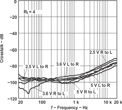 Figure 16. Crosstalk vs Frequency
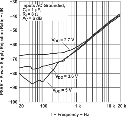 Figure 18. Power Supply Rejection Ratio
vs Frequency
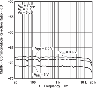 Figure 20. Common-Mode Rejection Ratio
vs Frequency
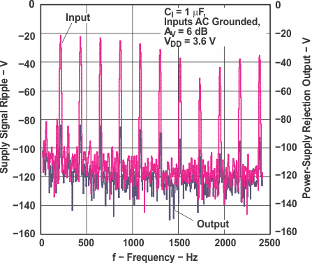 Figure 22. Power Supply Rejection vs Frequency
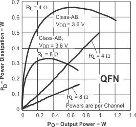 Figure 24. Power Dissipation vs Output Power
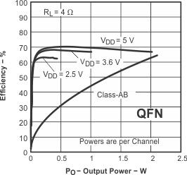 Figure 26. Efficiency vs Output Power
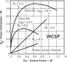 Figure 28. Power Dissipation vs Output Power
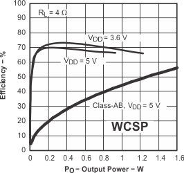 Figure 30. Efficiency vs Output Power
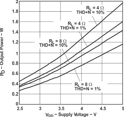 Figure 32. Output Power vs Supply Voltage