-
TPS6217x-Q1 具有 DCS-Control™ 功能的 3V 到 17V 0.5A 降压转换器 ZHCSD50D December 2014 – February 2017 TPS62170-Q1 , TPS62171-Q1 , TPS62172-Q1
PRODUCTION DATA.
-
TPS6217x-Q1 具有 DCS-Control™ 功能的 3V 到 17V 0.5A 降压转换器
- 1 特性
- 2 应用
- 3 说明
- 4 修订历史记录
- 5 Device Comparison Table
- 6 Pin Configuration and Functions
- 7 Specifications
- 8 Detailed Description
- 9 Application and Implementation
- 10Power Supply Recommendations
- 11Layout
- 12器件和文档支持
- 13机械、封装和可订购信息
- 重要声明
TPS6217x-Q1 具有 DCS-Control™ 功能的 3V 到 17V 0.5A 降压转换器
1 特性
- DCS-Control™拓扑
- 适用于汽车电子 应用
- 具有符合 AEC-Q100 标准的下列结果:
- 器件温度等级:-40°C 至 125°C 的运行结温范围
- 器件人体放电模式 (HBM) 静电放电 (ESD) 分类等级 H2
- 器件组件充电模式 (CDM) ESD 分类等级 C4B
- 输入电压范围:3V 至 17V
- 输出电流高达 500mA
- 可调输出电压范围为 0.9V 至 6V
- 固定输出电压版本
- 无缝省电模式转换
- 静态电流典型值为 17µA
- 电源正常输出
- 100% 占空比模式
- 短路保护
- 过热保护
- 与 TPS62160-Q1 引脚对引脚兼容
- 采用 2 × 2mm WSON-8 封装
- 借助 WEBENCH® 电源设计器并使用 TPS62170-Q1 创建定制设计方案
3 说明
TPS6217x-Q1 系列是一款简单易用的同步降压直流/直流转换器,针对 高功率密度的应用 进行了优化。该器件的开关频率典型值高达 2.25MHz,允许使用小型电感,利用 DCS-Control™ 拓扑技术提供快速瞬态响应并实现高输出电压精度。
此器件具有 3V 至 17V 宽运行输入电压范围,非常适用于由锂离子或其它电池以及 12V 中间电源轨供电的系统。其输出电压为 0.9V 至 6V,支持高达 0.5A 的持续输出电流(使用 100% 占空比模式)。
通过配置使能引脚和开漏电源正常状态引脚也可以实现电源排序。
在节能模式下,器件可根据输入电压 (VIN) 生成约 17μA 的静态电流。负载较小时可自动且无缝进入节能模式,同时该模式可保持整个负载范围内的高效率。在关断模式下,此器件会关闭且关断期间的流耗少于 2μA。
此器件分为可调和固定输出电压型号,采用 2mm × 2mm (DSG) 8 引脚 WSON 封装。
器件信息(1)
| 器件型号 | 封装 | 封装尺寸(标称值) |
|---|---|---|
| TPS62170-Q1 | WSON (8) | 2.00mm x 2.00mm |
| TPS62171-Q1 | WSON (8) | 2.00mm x 2.00mm |
| TPS62172-Q1 | WSON (8) | 2.00mm x 2.00mm |
- 要了解所有可用封装,请见数据表末尾的可订购产品附录。
典型应用电路原理图 |
效率与输出电流间的关系 |
|
|
空白 空白空白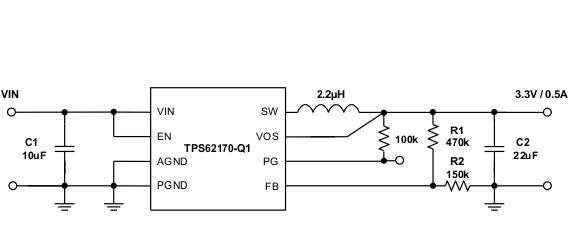 |
 |
|
4 修订历史记录
Changes from C Revision (November 2016) to D Revision
- Added WEBENCH® 信息Go
- Changed TJ spec MAX value From 125°C To 150°C in the Absolute Maximum Ratings tableGo
Changes from B Revision (October 2016) to C Revision
- Added 引脚对引脚兼容特性Go
- Changed Thermal Information tableGo
- Added C1, C2, R1, R2, descriptors to Figure 5Go
- Added C1, C2 to Table 1 Go
Changes from A Revision (September 2016) to B Revision
- Added the Device Comparison TableGo
Changes from * Revision (December 2014) to A Revision
- 在应用列表中将“同轴以太网供电 POL 电源”更改为“同轴电缆供电 POL 电源”Go
- Added 数据表中增加了 TPS62171-Q1 器件。Go
- Changed Unit from mA to V for Pin voltage at FB, PG, and VOS in the Absolute Maximum Ratings table. Go
- Changed Unit from °C to mA in the Absolute Maximum Ratings table for Power Good sink current. Go
- Changed Unit from kV to °C in the Absolute Maximum Ratings table for the Operating junction temperature, TJ Go
- Added legal NOTE at Application and Implementation Go
- Added cross references to Third-Party Products disclaimer in Table 1Go
5 Device Comparison Table
| PART NUMBER(1) | OUTPUT VOLTAGE |
|---|---|
| TPS62170-Q1 | adjustable |
| TPS62171-Q1 | 1.8 V |
| TPS62172-Q1 | 3.3 V |
6 Pin Configuration and Functions
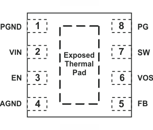
space
Pin Functions
| PIN(1) | I/O | DESCRIPTION | |
|---|---|---|---|
| NAME | NUMBER | ||
| PGND | 1 | Power ground | |
| VIN | 2 | I | Supply voltage |
| EN | 3 | I | Enable input (High = enabled, Low = disabled) |
| AGND | 4 | Analog ground | |
| FB | 5 | I | Voltage feedback of adjustable version. Connect resistive voltage divider to this pin. It is recommended to connect FB to AGND on fixed output voltage versions for improved thermal performance. |
| VOS | 6 | I | Output voltage sense pin and connection for the control loop circuitry. |
| SW | 7 | O | Switch node, which is connected to the internal MOSFET switches. Connect inductor between SW and output capacitor. |
| PG | 8 | O | Output power good (High = VOUT ready, Low = VOUT below nominal regulation) ; open drain (requires pull-up resistor; goes high impedance, when device is switched off) |
| Exposed Thermal Pad | Must be connected to AGND. Must be soldered to achieve appropriate power dissipation and mechanical reliability. | ||
7 Specifications
7.1 Absolute Maximum Ratings
over operating junction temperature range (unless otherwise noted) (1)| MIN | MAX | UNIT | ||
|---|---|---|---|---|
| Pin voltage(2) | VIN | –0.3 | 20 | V |
| EN | –0.3 | VIN+0.3 | ||
| SW | -0.3 | VIN+0.3 | V | |
| FB, PG, VOS | –0.3 | 7 | V | |
| Power Good sink current | PG | 10 | mA | |
| Operating junction temperature range, TJ | –40 | 150 | °C | |
| Storage temperature range, Tstg | –65 | 150 | °C | |
7.2 ESD Ratings
| VALUE | UNIT | ||||
|---|---|---|---|---|---|
| V(ESD) | Electrostatic discharge | Human body model (HBM), per AEC Q100-002(1) | ±2000 | V | |
| Charged device model (CDM), per AEC Q100-011 | ±500 | ||||
7.3 Recommended Operating Conditions
over operating junction temperature range (unless otherwise noted)| MIN | TYP | MAX | UNIT | ||
|---|---|---|---|---|---|
| VIN | Supply voltage | 3 | 17 | V | |
| VOUT | Output voltage range | 0.9 | 6 | V | |
| TJ | Operating junction temperature | –40 | 125 | °C | |
7.4 Thermal Information
| THERMAL METRIC(1) | TPS6217x-Q1 | UNIT | |
|---|---|---|---|
| DSG (8 PINS) | |||
| RθJA | Junction-to-ambient thermal resistance | 65.5 | °C/W |
| RθJC(top) | Junction-to-case (top) thermal resistance | 66.4 | °C/W |
| RθJB | Junction-to-board thermal resistance | 35.5 | °C/W |
| ψJT | Junction-to-top characterization parameter | 1.7 | °C/W |
| ψJB | Junction-to-board characterization parameter | 35.8 | °C/W |
| RθJC(bot) | Junction-to-case (bottom) thermal resistance | 8.4 | °C/W |
7.5 Electrical Characteristics
over junction temperature range (TJ = –40°C to +125°C), typical values at VIN = 12 V and TJ = 25°C (unless otherwise noted)| PARAMETER | TEST CONDITIONS | MIN | TYP | MAX | UNIT | ||
|---|---|---|---|---|---|---|---|
| SUPPLY | |||||||
| VIN | Input voltage range(1) | 3 | 17 | V | |||
| IQ | Operating quiescent current | EN = High, IOUT = 0 mA, Device not switching | 17 | 30 | µA | ||
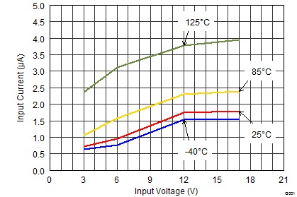
| ISD | Shutdown current(2) | EN = Low | 1.8 | 25 | µA | ||
| VUVLO | Undervoltage lockout threshold | Falling input voltage | 2.6 | 2.7 | 2.82 | V | |
| Hysteresis | 180 | mV | |||||
| TSD | Thermal shutdown temperature | 160 | °C | ||||
| Thermal shutdown hysteresis | 20 | ||||||
| CONTROL (EN, PG) | |||||||
| VEN_H | High-level input threshold voltage (EN) | 0.9 | V | ||||
| VEN_L | Low-level input threshold voltage (EN) | 0.3 | V | ||||
| ILKG_EN | Input leakage current (EN) | EN = VIN or GND | 0.01 | 1 | µA | ||
| VTH_PG | Power Good threshold voltage | Rising (%VOUT) | 92% | 95% | 98% | ||
| Falling (%VOUT) | 87% | 90% | 93% | ||||
| VOL_PG | Power Good output low | IPG = –2 mA | 0.07 | 0.3 | V | ||
| ILKG_PG | Input leakage current (PG) | VPG = 1.8 V | 1 | 400 | nA | ||
| POWER SWITCH | |||||||
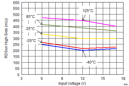
| RDS(ON) | High-side MOSFET ON-resistance | VIN ≥ 6 V | 300 | 600 | mΩ | ||
| VIN = 3 V | 430 | ||||||
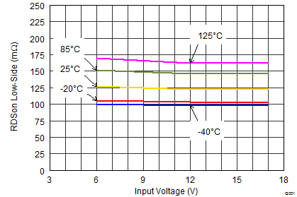
| Low-side MOSFET ON-resistance | VIN ≥ 6 V | 120 | 200 | mΩ | |||
| VIN = 3 V | 165 | ||||||
| ILIMF | High-side MOSFET forward current limit(3) | VIN = 12 V, TA = 25°C | 0.85 | 1.05 | 1.35 | A | |
| OUTPUT | |||||||
| VREF | Internal reference voltage | 0.8 | V | ||||
| ILKG_FB | Pin leakage current (FB) | TPS62170-Q1, VFB = 1.2 V | 5 | 400 | nA | ||
| VOUT | Output voltage range | TPS62170-Q1, VIN ≥ VOUT | 0.9 | 6.0 | V | ||
| Feedback voltage accuracy(4) | PWM Mode operation, VIN ≥ VOUT + 1 V | –3% | 3% | ||||
| Power Save Mode operation, COUT = 22 µF(5) | –3.5% | 4% | |||||
| DC output voltage load regulation(6) | VIN = 12 V, VOUT = 3.3 V, PWM Mode operation | 0.05 | % / A | ||||
| DC output voltage line regulation (6) | 3 V ≤ VIN ≤ 17 V, VOUT = 3.3 V, IOUT = 0.5 A, PWM Mode operation |
0.02 | % / V | ||||
7.6 Typical Characteristics
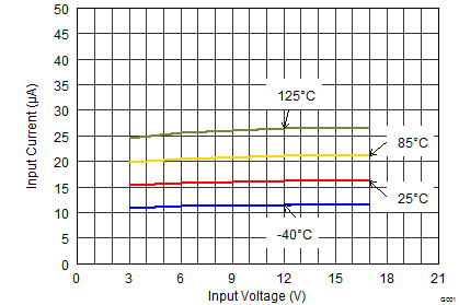
At VIN = 12 V, VOUT = 3.3 V and TJ = 25°C (unless otherwise noted)