-
TAS2552 4.0W D 类单声道音频放大器,支持 G 类升压和扬声器感测
- 1 特性
- 2 应用范围
- 3 说明
- 4 修订历史记录
- 5 Pin Configuration and Functions
- 6 Specifications
-
7 Detailed Description
- 7.1 Overview
- 7.2 Functional Block Diagram
- 7.3
Feature Description
- 7.3.1 General I2C Operation
- 7.3.2 Single-Byte and Multiple-Byte Transfers
- 7.3.3 Single-Byte Write
- 7.3.4 Multiple-Byte Write and Incremental Multiple-Byte Write
- 7.3.5 Single-Byte Read
- 7.3.6 Multiple-Byte Read
- 7.3.7 PLL
- 7.3.8 Gain Settings
- 7.3.9 Class-D Edge Rate Control
- 7.3.10 Battery Tracking AGC
- 7.3.11 Configurable Boost Current Limit (ILIM)
- 7.4 Device Functional Modes
- 7.5
Register Map
- 7.5.1 Register Map Summary
- 7.5.2 Register 0x00: Device Status Register
- 7.5.3 Register 0x01: Configuration Register 1
- 7.5.4 Register 0x02: Configuration Register 2
- 7.5.5 Register 0x03: Configuration Register 3
- 7.5.6 Register 0x04: DOUT Tristate Mode
- 7.5.7 Register 0x05: Serial Interface Control Register 1
- 7.5.8 Register 0x06: Serial Interface Control Register 2
- 7.5.9 Register 0x07: Output Data Register
- 7.5.10 Register 0x08: PLL Control Register 1
- 7.5.11 Register 0x09: PLL Control Register 2
- 7.5.12 Register 0x0A: PLL Control Register 3
- 7.5.13 Register 0x0B: Battery Tracking Inflection Point Register
- 7.5.14 Register 0x0C: Battery Tracking Slope Control Register
- 7.5.15 Register 0x0D: Reserved Register
- 7.5.16 Register 0x0E: Battery Tracking Limiter Attack Rate and Hysteresis Time
- 7.5.17 Register 0x0F: Battery Tracking Limiter Release Rate
- 7.5.18 Register 0x10: Battery Tracking Limiter Integration Count Control
- 7.5.19 Register 0x11: PDM Configuration Register
- 7.5.20 Register 0x12: PGA Gain Register
- 7.5.21 Register 0x13: Class-D Edge Rate Control Register
- 7.5.22 Register 0x14: Boost Auto-Pass Through Control Register
- 7.5.23 Register 0x15: Reserved Register
- 7.5.24 Register 0x16: Version Number
- 7.5.25 Register 0x17: Reserved Register
- 7.5.26 Register 0x18: Reserved Register
- 7.5.27 Register 0x19: VBAT Data Register
- 8 Applications and Implementation
- 9 Power Supply Recommendations
- 10Layout
- 11器件和文档支持
- 12机械、封装和可订购信息
- 重要声明
DATA SHEET
TAS2552 4.0W D 类单声道音频放大器,支持 G 类升压和扬声器感测
本资源的原文使用英文撰写。 为方便起见,TI 提供了译文;由于翻译过程中可能使用了自动化工具,TI 不保证译文的准确性。 为确认准确性,请务必访问 ti.com 参考最新的英文版本(控制文档)。
1 特性
- 模拟或数字输入单声道升压 D 类放大器
- 为 8Ω 负载提供 4.0 W 功率,供电方式为 4.2 V 电源(1% 总谐波失真 (THD) + N)
- 额定功率下,效率达到 85%
- I2S,左侧对齐,右侧对齐,数字信号处理器 (DSP),脉冲密度调制 (PDM),以及时分复用 (TDM) 输入和输出接口
- 输入采样速率从 8kHz 至 192kHz
- 高效 G 类升压转换器
- 自动调节 D 类电源
- 内置扬声器感测
- 测量扬声器电流和电压
- 测量 VBAT 和 VBOOST 电压
- 内置自动增益控制 (AGC)
- 限制电池流耗
- 可调 D 类开关边缘速率控制
- 电源
- 升压输入:3.0V 至 5.5V
- 模拟:1.65V 至 1.95V
- 数字 I/O:1.5V 至 3.6V
- 过热和短路保护
- 用于寄存器控制的 I2C 接口
- 使用两个 TAS2552 的立体声配置
- I2C 地址选择端子 (ADDR)
- 2.855mm x 2.575mm,0.4mm 焊球间距,30 焊球晶圆级芯片封装 (WCSP)
2 应用范围
- 移动电话
- 便携式导航设备 (PND)
- 便携式音频底座
- 平板电脑
- 游戏设备
3 说明
TAS2552 是一款高效 D 类音频功率放大器,此放大器具有高级电池电流管理功能和集成 G 类升压转换器。 此器件持续测量负载上的电流和电压,并且提供此类信息的数字流。
G 类升压转换器生成 D 类放大器电源轨。 低 D 类输出功率期间,此升压转换器通过使 VBAT 无效并将其直接接至 D 类放大器电源来提升效率。 当需要高功率音频时,升压转换器快速激活,以提供比直接接至电池的单独放大器高很多的音频。
AGC 自动调节 D 类增益,以减少充电结束电压上的电池电流,从而防止输出削波、失真和早期系统关断。 通过 I2C 调节固定增益。 增益范围介于 -7dB 至 +24dB 之间(步长 1dB)。
除了差分单声道模拟输入,TAS2552 具有使用数字输入的内置 16 位数模 (D/A) 转换器。 将 D/A 转换器从数字主机处理器移至集成放大器的工艺能够以更低的系统成本提供更佳的动态性能。 此外,由于印刷电路板 (PCB) 传输的是数字信号而非模拟信号,所以系统级上对于外部干扰(例如 GSM 帧速率噪声)的敏感度被减少。
器件信息
| 订货编号 | 封装 | 封装尺寸 |
|---|---|---|
| TAS2552YFF | WCSP (30) | 2.855mm x 2.575mm |

4 修订历史记录
Changes from A Revision (February 2014) to B Revision
- Added clarification on EN Pin Function and ConfigurationGo
- Changed VBAT MAX = 2.45 V. Added footnote to avoid VBAT reset.Go
- Added clarification on wait time regarding DEV_RESET RegisterGo
- Added clarification on VBAT reset range for normal operation mode.Go
Changes from * Revision (January 2014) to A Revision
- Changed 数据表状态,从产品预览改为量产数据Go
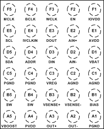
5 Pin Configuration and Functions
30-Ball WCSP
YFF Package
(Top View)

Pin Functions
| TERMINAL | INPUT/OUTPUT/POWER | DESCRIPTION | |
|---|---|---|---|
| NAME | BALL WCSP | ||
| PGND | A1 | P | Power ground. Connect to high current ground plane. |
| OUT– | A2 | O | Inverting Class D output. |
| OUT+ | A3 | O | Non-inverting Class D output. |
| PVDD | A4 | P | Class-D power supply. Connected internally to VBOOST – do not drive this terminal externally. |
| VBOOST | A5 | P | 8.5 V boost output. Connected internally to PVDD – do not drive this terminal externally. |
| BIAS | B1 | O | Mid-rail reference for Class D channel. |
| VSENSE– | B2 | I | Inverting voltage sense input. |
| VSENSE+ | B3 | I | Non-inverting voltage sense input. |
| SW | B4,B5 | I/O | Boost switch terminal. |
| AGND | C1,C2 | P | Analog ground. Connect to low noise ground plane. |
| VREG | C3 | O | High-side FET gate drive boost converter. |
| PGND | C4,C5 | P | Power ground. Connect to high current ground plane. |
| VBAT | D1 | P | Battery power supply. Connect to 3.0 V to 5.5 V battery supply. |
| AIN– | D2 | I | Inverting analog input. |
| DIN | D3 | I | Audio serial data input. Format is I2S, LJF, RJF, or TDM data. |
| ADDR | D4 | I | I2C address select terminal. Set ADDR = GND for device 7-bit address 0x40; set ADDR = IOVDD for 7-bit address 0x41. |
| SDA | D5 | I/O | I2C control bus data. |
| AVDD | E1 | P | Analog low voltage supply terminal. Connect to 1.65 V to 1.95 V supply. |
| AIN+ | E2 | I | Non-inverting analog input. |
| DOUT | E3 | O | Serial I/V digital output. Format is I2S, LJF, RJF, TDM, or undecimated PDM data. |
| IVCLKIN | E4 | I | Serial clock input for undecimated PDM I/V data. |
| SCL | E5 | I | I2C control bus clock. |
| EN(1) | F2 | I | Device enable (HIGH = Normal Operation, LOW = Standby) |
| WCLK | F3 | I | Audio serial word clock. |
| BCLK | F4 | I | Audio serial bit clock. |
| MCLK | F5 | I | External master clock. |
| IOVDD | F1 | P | Supply for digital input and output levels. Voltage range is 1.5 V to 3.6 V. |
(1) Wait a minimum of 1ms after EN is pulled high or DEV_RESET is issued before accessing the control interface. EN=low will erase the TAS2552 device configuration. The TAS2552 device must be configured (see Initialization) after EN=high.