-
ADS4249 双通道、14 位、250MSPS 超低功耗 ADC
- 1 特性
- 2 应用
- 3 说明
- 4 修订历史记录
- 5 ADS424x, ADS422x Family Comparison
- 6 Pin Configuration and Functions
-
7 Specifications
- 7.1 Absolute Maximum Ratings
- 7.2 ESD Ratings
- 7.3 Recommended Operating Conditions
- 7.4 Thermal Information
- 7.5 Electrical Characteristics: ADS4249 (250 MSPS)
- 7.6 Electrical Characteristics: General
- 7.7 Digital Characteristics
- 7.8 LVDS and CMOS Modes Timing Requirements
- 7.9 LVDS Timings at Lower Sampling Frequencies
- 7.10 CMOS Timings at Lower Sampling Frequencies
- 7.11 Serial Interface Timing Characteristics
- 7.12 Reset Timing (Only when Serial Interface is Used)
- 7.13 Typical Characteristics
-
8 Detailed Description
- 8.1 Overview
- 8.2 Functional Block Diagram
- 8.3 Feature Description
- 8.4 Device Functional Modes
- 8.5 Programming
- 8.6
Register Maps
- 8.6.1 Serial Register Map
- 8.6.2
Description of Serial Registers
- 8.6.2.1 Register Address 00h (Default = 00h)
- 8.6.2.2 Register Address 01h (Default = 00h)
- 8.6.2.3 Register Address 01h (Default = 00h)
- 8.6.2.4 Register Address 25h (Default = 00h)
- 8.6.2.5 Register Address 29h (Default = 00h)
- 8.6.2.6 Register Address 2Bh (Default = 00h)
- 8.6.2.7 Register Address 3Dh (Default = 00h)
- 8.6.2.8 Register Address 3Fh (Default = 00h)
- 8.6.2.9 Register Address 40h (Default = 00h)
- 8.6.2.10 Register Address 41h (Default = 00h)
- 8.6.2.11 Register Address 42h (Default = 00h)
- 8.6.2.12 Register Address 45h (Default = 00h)
- 8.6.2.13 Register Address 4Ah (Default = 00h)
- 8.6.2.14 Register Address 58h (Default = 00h)
- 8.6.2.15 Register Address BFh (Default = 00h)
- 8.6.2.16 Register Address C1h (Default = 00h)
- 8.6.2.17 Register Address CFh (Default = 00h)
- 8.6.2.18 Register Address EFh (Default = 00h)
- 8.6.2.19 Register Address F1h (Default = 00h)
- 8.6.2.20 Register Address F2h (Default = 00h)
- 8.6.2.21 Register Address 2h (Default = 00h)
- 8.6.2.22 Register Address D5h (Default = 00h)
- 8.6.2.23 Register Address D7h (Default = 00h)
- 8.6.2.24 Register Address DBh (Default = 00h)
- 9 Application and Implementation
- 10Power Supply Recommendations
- 11Layout
- 12器件和文档支持
- 13机械、封装和可订购信息
- 重要声明
ADS4249 双通道、14 位、250MSPS 超低功耗 ADC
1 特性
- 最大采样率:250MSPS
- 1.8V 单电源供电,具有超低功耗:
- 250MSPS 时的总功耗为 560mW
- 高动态性能:
- 170MHz 时的无杂散动态范围 (SFDR) 为 80dBc
- 170MHz 时的信噪比 (SNR) 为 71.7dBFS
- 串扰:185MHz 时大于 90dB
- 可编程增益最高达 6dB,可权衡
SNR/SFDR 性能 - DC 偏移校正
- 输出接口选项:
- 1.8V 并行 CMOS 接口
- 支持可编程摆幅的双倍数据速率 (DDR) 低压动态信令 (LVDS):
- 标准摆幅:350mV
- 低摆幅:200mV
- 支持低输入时钟振幅
低至 200mVPP - 封装: 64 引脚 9mm × 9mm 超薄型四方扁平无引线 (VQFN) 封装
2 应用
- 无线通信基础设施
- 软件定义的无线电
- 功率放大器线性化
3 说明
ADS4249 属于 ADS42xx 双通道、12 位和 14 位模数转换器 (ADC) 超低功耗系列产品。该器件凭借创新设计技术实现了高动态性能,并且采用 1.8V 电源供电运行,功耗极低。该拓扑使 ADS4249 非常适合多载波、高带宽通信 应用。
ADS4249 具有增益选项,可用于提升在较小满量程输入范围内的 SFDR 性能。这个器件还包括一个 DC 偏移校正环路,可用于消除 ADC 偏移。DDR LVDS 与并行 CMOS 数字输出接口都采用紧凑型 VQFN-64 封装。 PowerPAD™封装。
此器件包含内部基准,并消除了传统基准引脚与相关去耦电容。ADS4249 的额定工业温度范围为 -40°C 至 85°C。
器件信息(1)
| 器件型号 | 封装 | 封装尺寸(标称值) |
|---|---|---|
| ADS4249 | VQFN (64) | 9.00mm x 9.00mm |
- 要了解所有可用封装,请见数据表末尾的可订购产品附录。
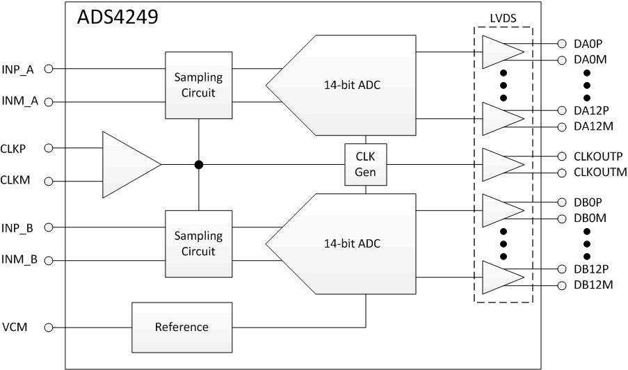
ADS4249 框图

4 修订历史记录
Changes from D Revision (May 2015) to E Revision
- Changed Pin Functions (LVDS Mode) table to comply with RGC Package (LVDS Mode) pin out diagramGo
- Changed Pin Functions (CMOS Mode) table to comply with RGC Package (CMOS Mode) pin out diagram Go
- Changed unit in last row of Clock Input, Input clock amplitude differential parameter to VPP in Recommended Operating Conditions tableGo
- Added text reference for Table 5 Go
Changes from C Revision (July 2012) to D Revision
- Added 引脚配置和功能部分,ESD 额定值表,特性 描述 部分,器件功能模式,应用和实施部分,电源相关建议部分,布局部分,器件和文档支持部分以及机械、封装和可订购信息部分Go
Changes from B Revision (September 2011) to C Revision
- Changed footnote 1 in CMOS Timings at Lower Sampling FrequenciesGo
- Changed conditions for ADS4249 Typical Characteristics sectionGo
- Changed register D5h bit names of bits D7, D4, D3, and D0 in Table 10Go
- Changed register address D8 to DB in Table 10Go
- Changed register address D5h to match change in Table 10Go
- Changed register address DB to match change in Table 10Go
Changes from A Revision (September 2011) to B Revision
5 ADS424x, ADS422x Family Comparison(1)
| 65 MSPS | 125 MSPS | 160 MSPS | 250 MSPS | |
|---|---|---|---|---|
| ADS422x 12-bit family |
ADS4222 | ADS4225 | ADS4226 | ADS4229 |
| ADS424x 14-bit family |
ADS4242 | ADS4245 | ADS4246 | ADS4249 |
The ADS4249 is pin-compatible with the previous generation ADS62P49 data converter; this similar architecture enables easy migration. However, there are some important differences between the two device generations, summarized in Table 1.
Table 1. Migrating from the ADS62P49
| ADS62P49 | ADS4249 |
|---|---|
| PINS | |
| Pin 22 is NC (not connected) | Pin 22 is AVDD |
| Pins 38 and 58 are DRVDD | Pins 38 and 58 are NC (do not connect, must be floated) |
| Pins 39 and 59 are DRGND | Pins 39 and 59 are NC (do not connect, must be floated) |
| SUPPLY | |
| AVDD is 3.3 V | AVDD is 1.8 V |
| DRVDD is 1.8 V | No change |
| INPUT COMMON-MODE VOLTAGE | |
| VCM is 1.5 V | VCM is 0.95 V |
| SERIAL INTERFACE | |
| Protocol: 8-bit register address and 8-bit register data | No change in protocol New serial register map |
| EXTERNAL REFERENCE | |
| Supported | Not supported |