-
DRV8833 双路 H 桥电机驱动器
DATA SHEET
DRV8833 双路 H 桥电机驱动器
本资源的原文使用英文撰写。 为方便起见,TI 提供了译文;由于翻译过程中可能使用了自动化工具,TI 不保证译文的准确性。 为确认准确性,请务必访问 ti.com 参考最新的英文版本(控制文档)。
1 特性
2 应用
- 电池供电式玩具
- 服务点 (POS) 打印机
- 视频安保摄像机
- 办公自动化设备
- 游戏机
- 机器人
3 说明
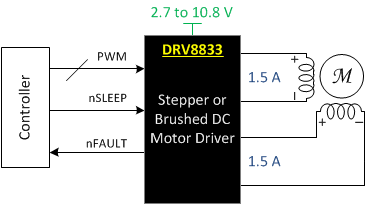
DRV8833器件为玩具、打印机及其他机电一体化应用提供了一款双桥电机驱动器 解决方案。
该器件具有两个 H 桥驱动器,能够驱动两部直流刷式电机、一部双极步进电机、多个螺线管或其他感性负载。
每个 H 桥的输出驱动器模块由配置为 H 桥的 N 沟道功率 MOSFET 组成,用于驱动电机绕组。每个 H 桥均具备调节或限制绕组电流的电路。
该器件利用故障输出引脚实现内部关断功能,提供过流保护、短路保护、欠压锁定和过热保护。另外,还提供了一种低功耗休眠模式。
DRV8833 采用带有 PowerPAD™16 引脚超薄型四方扁平无引线 (WQFN) 封装(环保型:符合 RoHS 标准且不含锑/溴)。
器件信息(1)
| 器件型号 | 封装 | 封装尺寸(标称值) |
|---|---|---|
| DRV8833 | TSSOP (16) | 5.00mm x 4.40mm |
| HTSSOP (16) | 5.00mm x 4.40mm | |
| WQFN (16) | 4.00mm x 4.00mm |
- 要了解所有可用封装,请见数据表末尾的可订购产品附录。
简化电路原理图

4 修订历史记录
Changes from D Revision (March 2015) to E Revision
- 已更新特性分项,以包括其他封装规范Go
- Added note back to Pin Functions regarding the different I/O types Go
- Corrected the device name and current regulation description in Overview Go
- Corrected output current to 1.5-A RMS from 700-mA RMS Go
Changes from C Revision (January 2013) to D Revision
- Added ESD 额定值表,特性 描述部分,器件功能模式,应用和实施部分,电源相关建议部分,布局部分,器件和文档支持部分以及机械、封装和可订购信息部分 Go
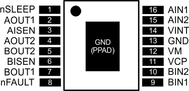
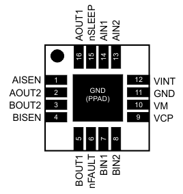
5 Pin Configuration and Functions
PWP Package
16-Pin HTSSOP
Top View

PW Package
16-Pin TSSOP
Top View

RTY Package
16-Pin WQFN
Top View

Pin Functions
| PIN | I/O(1) | DESCRIPTION | EXTERNAL COMPONENTS OR CONNECTIONS |
||
|---|---|---|---|---|---|
| NAME | WQFN | HTSSOP, TSSOP |
|||
| POWER AND GROUND | |||||
| GND | 11 PPAD |
13 | — | Device ground. HTSSOP package has PowerPAD. | Both the GND pin and device PowerPAD must be connected to ground. |
| VINT | 12 | 14 | — | Internal supply bypass | Bypass to GND with 2.2-μF, 6.3-V capacitor. |
| VM | 10 | 12 | — | Device power supply | Connect to motor supply. A 10-µF (minimum) ceramic bypass capacitor to GND is recommended. |
| VCP | 9 | 11 | IO | High-side gate drive voltage | Connect a 0.01-μF, 16-V (minimum) X7R ceramic capacitor to VM. |
| CONTROL | |||||
| AIN1 | 14 | 16 | I | Bridge A input 1 | Logic input controls state of AOUT1. Internal pulldown. |
| AIN2 | 13 | 15 | I | Bridge A input 2 | Logic input controls state of AOUT2. Internal pulldown. |
| BIN1 | 7 | 9 | I | Bridge B input 1 | Logic input controls state of BOUT1. Internal pulldown. |
| BIN2 | 8 | 10 | I | Bridge B input 2 | Logic input controls state of BOUT2. Internal pulldown. |
| nSLEEP | 15 | 1 | I | Sleep mode input | Logic high to enable device, logic low to enter low-power sleep mode and reset all internal logic. Internal pulldown. |
| STATUS | |||||
| nFAULT | 6 | 8 | OD | Fault output | Logic low when in fault condition (overtemperature, overcurrent) |
| OUTPUT | |||||
| AISEN | 1 | 3 | IO | Bridge A ground / ISENSE | Connect to current sense resistor for bridge A, or GND if current control not needed |
| BISEN | 4 | 6 | IO | Bridge B ground / ISENSE | Connect to current sense resistor for bridge B, or GND if current control not needed |
| AOUT1 | 16 | 2 | O | Bridge A output 1 | Connect to motor winding A |
| AOUT2 | 2 | 4 | O | Bridge A output 2 | |
| BOUT1 | 5 | 7 | O | Bridge B output 1 | Connect to motor winding B |
| BOUT2 | 3 | 5 | O | Bridge B output 2 | |
(1) I = Input, O = Output, OZ = Tri-state output, OD = Open-drain output, IO = Input/output