-
Interleaved and Multiphase Inverting Buck-Boost Converter Reference Design
- 1
- Description
- Features
- Applications
- 1System Specification
-
2Results
- 2.1 Efficiency Graph, Voltage Mode
- 2.2 Efficiency Data, Voltage Mode
- 2.3 Efficiency Graph, Current Mode
- 2.4 Efficiency Data, Current Mode
- 2.5 Load Regulation, Voltage Mode
- 2.6 Load Regulation, Current Mode
- 2.7 Line Regulation, Voltage Mode
- 2.8 Line Regulation, Current Mode
- 2.9 Thermal Images, Voltage Mode
- 2.10 Thermal Image, Current Mode
-
3Waveforms
- 3.1 Prebias Start-Up, Voltage Mode
- 3.2 Prebias Start-up, Current Mode
- 3.3 Output Voltage Ripple, Voltage Mode
- 3.4 Output Voltage Ripple, Current Mode
- 3.5 Load Transient, Voltage Mode
- 3.6 Load Transient, Current Mode
- 3.7 Line Transient, Voltage Mode
- 3.8 Line Transient, Current Mode
- 3.9 Phase Current Balancing, Voltage Mode
- 3.10 Phase Current Balancing, Current Mode
- 3.11 Loop Response, Voltage Mode
- 3.12 Loop Response, Current Mode
- IMPORTANT NOTICE
Test Report
Interleaved and Multiphase Inverting Buck-Boost Converter Reference Design
Description
This reference design uses the UCD3138064A device as a digital controller to control inverting buck-boost. The design is capable of supporting two-phase peak current mode control or three-phase voltage mode control. The soft-switching technology is used in this design to improve the power efficiency. The input voltage is from –36 V to –62 V. The output voltage is adjustable from 28 V to 52 V. The default output voltage is 48 V and the maximum current is 14 A in two-phase peak current mode control or 21 A in three-phase voltage mode control.
Features
- High efficiency above 97.1%
- Interleaved two-phase peak current mode (PCM) control or three-phase with voltage mode control
- Zero voltage switching of MOSFETs
- Prebias start-up
- Current balancing between phases
- GUI-configurable to design a power supply based on requirements
Applications
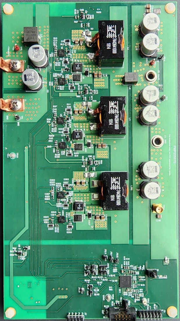
 Top Side
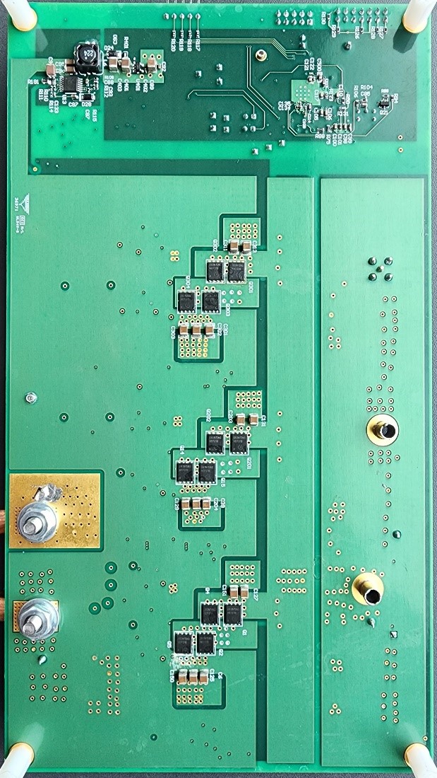
 Bottom Side