-
GaN-Based, 6.6-kW, Bidirectional, Onboard Charger Reference Design
GaN-Based, 6.6-kW, Bidirectional, Onboard Charger Reference Design
1 Description
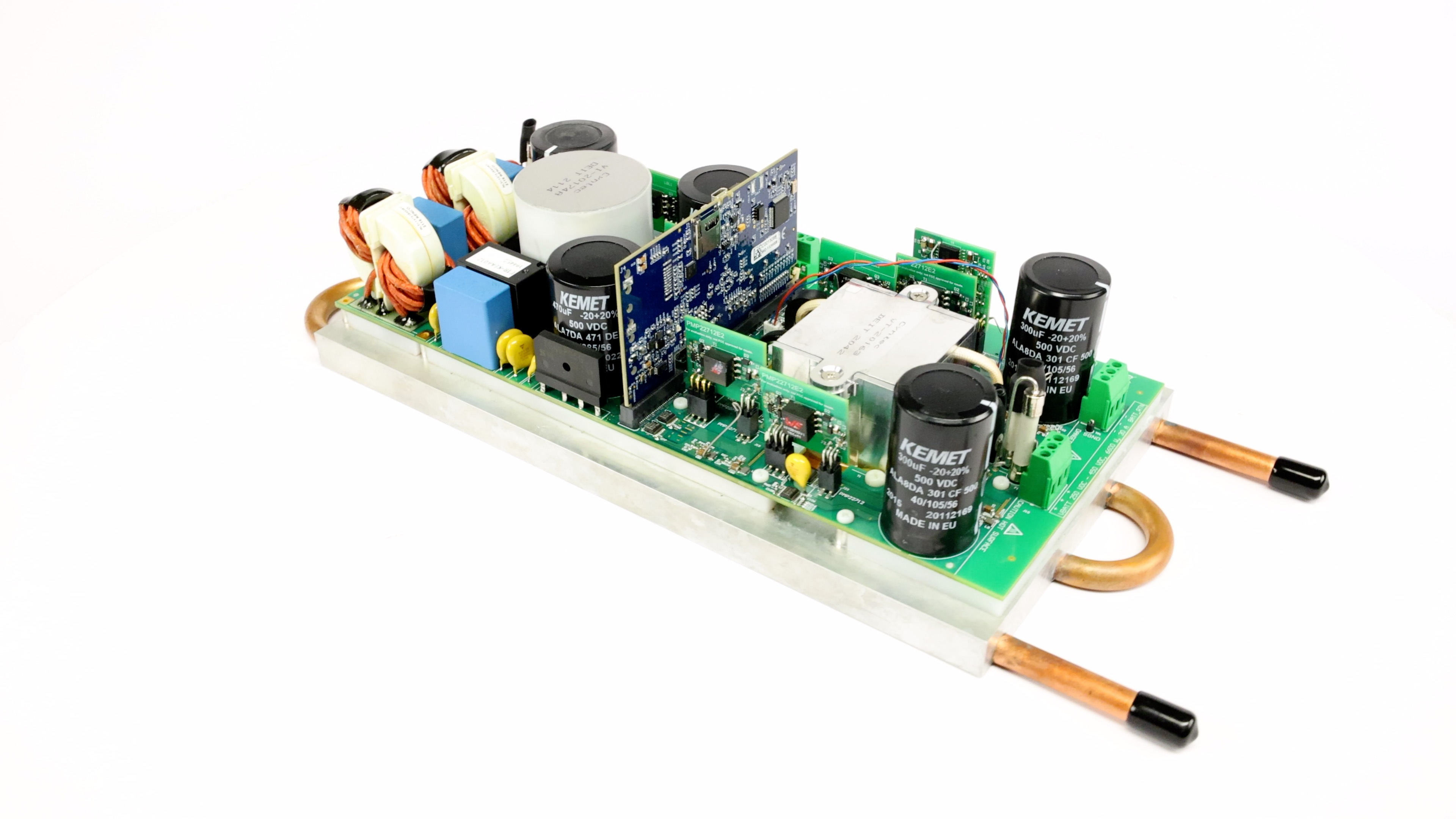
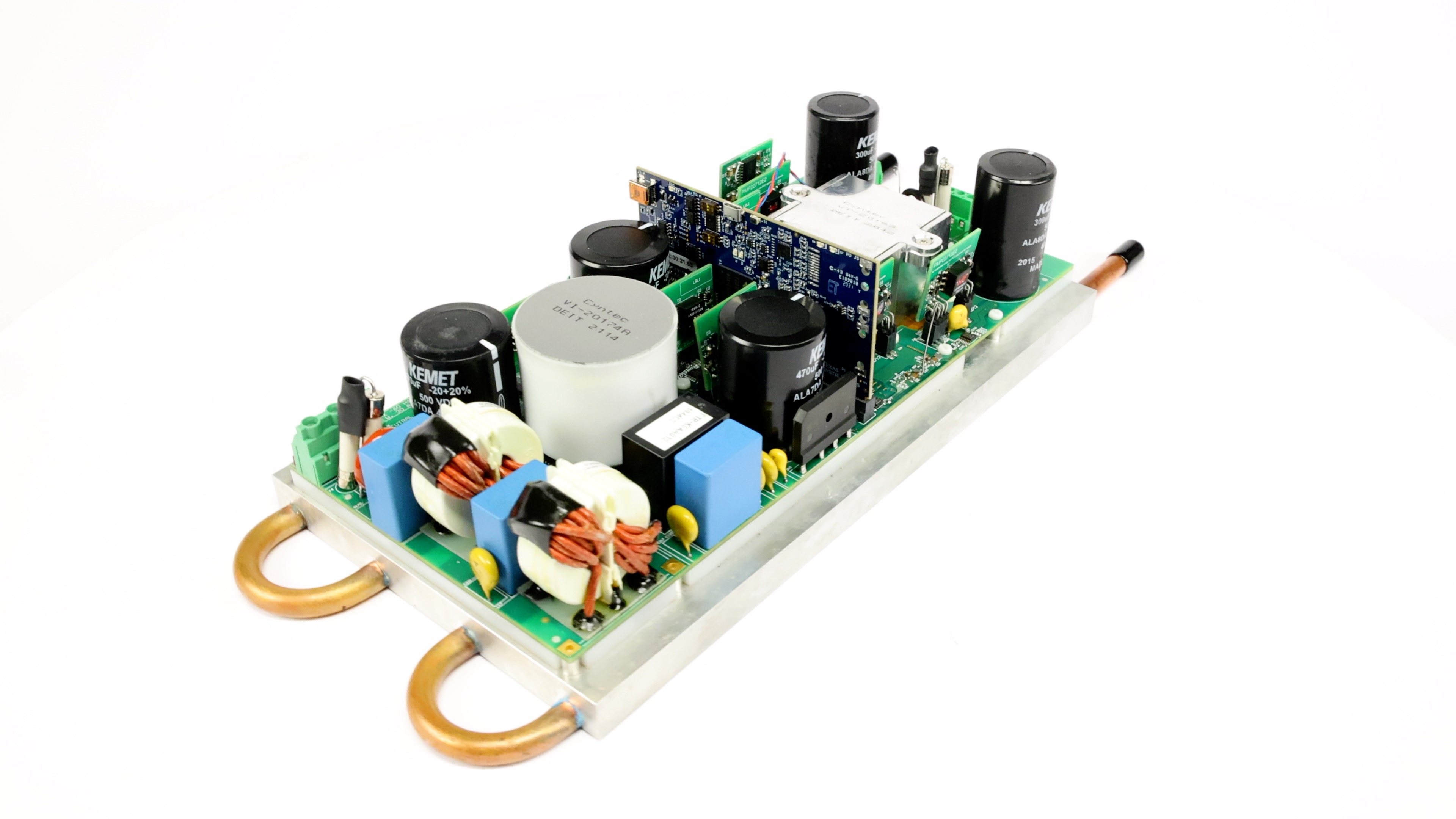
The PMP22650 reference design is a 6.6-kW, bidirectional, onboard charger. The design employs a two-phase totem pole PFC and a full-bridge CLLLC converter with synchronous rectification. The CLLLC utilizes both frequency and phase modulation to regulate the output across the required regulation range. The design uses a single processing core inside a TMS320F28388D microcontroller to control both the PFC and CLLLC. Synchronous rectification is implemented via the same microcontroller with Rogowski coil current sensors. High density is achieved through the use of high-speed GaN switches (LMG3522). The PFC is operating at 120 kHz and the CLLLC runs with a variable frequency from 200 kHz to 800 kHz. A peak system efficiency of 96.5% was achieved with an open-frame power density of 3.8 kW/L.
While the design calculations were done for a 6.6-kW output power, the design represents a suitable starting point for a 7.x-kW (for example, 7.2-kW to 7.4-kW) rated OBC operating from a 240-V input with a 32-A breaker.
 Figure 1-1 OBC Front View
 Figure 1-2 OBC Back View
 Figure 1-3 Simplified Schematic
2 Test Prerequisites
2.1 Voltage and Current Requirements
| Parameter | Min | Typ | Max | Units |
|---|---|---|---|---|
| AC Input Voltage | 90 | 240 | 264 | V |
| AC Input Current | 32 | A | ||
| DC Output Voltage | 250 | 400 | 450 | V |
| DC Output Current (Constant Current mode) | 20 | A | ||
| DC Output Power (Constant Power mode), VIN > 210 VRMS | 6.6 | kW |