• Menu
  • Product
  • Email
  • PDF
  • Order now
  • TMCS1107-Q1Functional Safety FIT Rate, FMD and Pin FMA

    • SFFS118 March   2021 TMCS1107-Q1


  • CONTENTS
  • SEARCH
  • TMCS1107-Q1Functional Safety FIT Rate, FMD and Pin FMA
  1. 1Overview
  2. 2Functional Safety Failure In Time (FIT) Rates
  3. 3Failure Mode Distribution (FMD)
  4. 4Pin Failure Mode Analysis (Pin FMA)
  5. IMPORTANT NOTICE
search No matches found.
  • Full reading width
    • Full reading width
    • Comfortable reading width
    • Expanded reading width
  • Card for each section
  • Card with all content


FUNCTIONAL SAFETY FIT RATE, FMD AND PIN-FMA

TMCS1107-Q1Functional Safety FIT Rate, FMD and Pin FMA

1 Overview

This document contains information for TMCS1107-Q1 (SOIC-8 package) to aid in a functional safety system design. Information provided are:

  • Functional Safety Failure In Time (FIT) rates of the semiconductor component estimated by the application of industry reliability standards
  • Component failure modes and their distribution (FMD) based on the primary function of the device
  • Pin failure mode analysis (Pin FMA)

Figure 1-1 shows the device functional block diagram for reference.
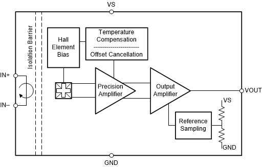
GUID-CF70504B-B846-486A-BDB8-9FDB5E5B3177-low.gif Figure 1-1 TMCS1107-Q1 Functional Block Diagram

The was developed using a quality-managed development process, but was not developed in accordance with the IEC 61508 or ISO 26262 standards.

ADVANCE INFORMATION for preproduction products; subject to change without notice.

2 Functional Safety Failure In Time (FIT) Rates

This section provides Functional Safety Failure In Time (FIT) rates for TMCS1107-Q1 based on two different industry-wide used reliability standards:

  • Table 2-1 provides FIT rates based on IEC TR 62380 / ISO 26262 part 11
  • Table 2-2 provides FIT rates based on the Siemens Norm SN 29500-2
Table 2-1 Component Failure Rates per IEC TR 62380 / ISO 26262 Part 11
FIT IEC TR 62380 / ISO 26262FIT (Failures Per 109 Hours)
Total Component FIT Rate18
Die FIT Rate9
Package FIT Rate9

The failure rate and mission profile information in Table 2-1 comes from the Reliability data handbook IEC TR 62380 / ISO 26262 part 11:

  • Mission Profile: Motor Control from Table 11
  • Power dissipation: 1750 mW
  • Climate type: World-wide Table 8
  • Package factor (lambda 3): Table 17b
  • Substrate Material: FR4
  • EOS FIT rate assumed: 0 FIT
Table 2-2 Component Failure Rates per Siemens Norm SN 29500-2
TableCategoryReference FIT RateReference Virtual TJ
5 CMOS/BICMOS ASICs Analog & Mixed =<50V supply25 FIT55°C

The Reference FIT Rate and Reference Virtual TJ (junction temperature) in Table 2-2 come from the Siemens Norm SN 29500-2 tables 1 through 5. Failure rates under operating conditions are calculated from the reference failure rate and virtual junction temperature using conversion information in SN 29500-2 section 4.

3 Failure Mode Distribution (FMD)

The failure mode distribution estimation for TMCS1107-Q1 in Table 3-1 comes from the combination of common failure modes listed in standards such as IEC 61508 and ISO 26262, the ratio of sub-circuit function size and complexity and from best engineering judgment.

The failure modes listed in this section reflect random failure events and do not include failures due to misuse or overstress.

Table 3-1 Die Failure Modes and Distribution
Die Failure ModesFailure Mode Distribution (%)
OUT open (High-Z)25%
OUT to GND20%
OUT to VS20%
OUT functional, not in specification35%

The FMD in Table 3-1 excludes short circuit faults across the isolation barrier. Faults for short circuit across the isolation barrier can be excluded according to ISO 61800-5-2:2016 if the following requirements are fulfilled:

  1. The signal isolation component is OVC III according to IEC 61800-5-1. If a SELV/PELV power supply is used, pollution degree 2/OVC II applies. All requirements of IEC 61800-5-1:2007, 4.3.6 apply.
  2. Measures are taken to ensure that an internal failure of the signal isolation component cannot result in excessive temperature of its insulating material.

Creepage and clearance requirements should be applied according to the specific equipment isolation standards of an application. Care should be taken to maintain the creepage and clearance distance of a board design to ensure that the mounting pads of the isolator on the printed-circuit board do not reduce this distance.

4 Pin Failure Mode Analysis (Pin FMA)

This section provides a Failure Mode Analysis (FMA) for the pins of the TMCS1107-Q1. The failure modes covered in this document include the typical pin-by-pin failure scenarios:

  • Pin short-circuited to Ground (see Table 4-2)
  • Pin open-circuited (see Table 4-3)
  • Pin short-circuited to an adjacent pin (see Table 4-4)
  • Pin short-circuited to supply (see Table 4-5)

Table 4-2 through Table 4-5 also indicate how these pin conditions can affect the device as per the failure effects classification in Table 4-1.

Table 4-1 TI Classification of Failure Effects
Class Failure Effects
A Potential device damage that affects functionality
B No device damage, but loss of functionality
C No device damage, but performance degradation
D No device damage, no impact to functionality or performance

Figure 4-1 shows the TMCS1107-Q1 pin diagram. For a detailed description of the device pins please refer to the Pin Configuration and Functions section in the TMCS1107-Q1 data sheet.

GUID-79B13529-3FE9-484F-8946-17079038EB89-low.gif Figure 4-1 TMCS1107-Q1 Pin Diagram

Following are the assumptions of use and the device configuration assumed for the pin FMA in this section:

  • TA=-40°C to 125°C
  • VS=3V to 5.5V
  • VCM=-600V to 600V
  • VREF=0V to VS
Table 4-2 Pin FMA for Device Pins Short-Circuited to Ground
Pin Name Pin No. Description of Potential Failure Effect(s) Failure Effect Class
IN+ 1 For forward current, hall-sensor bypassed, providing no signal to be sensed and amplified. If IN+ is at a large potential above GND, this will result in a lot of current being sunk. Depending upon layout and configuration, this could damage the input current system supply, the load device, or the TMCS1100. A
IN+ 2 For forward current, hall-sensor bypassed, providing no signal to be sensed and amplified. If IN+ is at a large potential above GND, this will result in a lot of current being sunk. Depending upon layout and configuration, this could damage the input current system supply, the load device, or the TMCS1100. A
IN- 3 For reverse current, hall-sensor bypassed, providing no signal to be sensed and amplified. If IN- is at a large potential above GND, this will result in a lot of current being sunk. Depending upon layout and configuration, this could damage the input current system supply, the load device, or the TMCS1100. A
IN- 4 For reverse current, hall-sensor bypassed, providing no signal to be sensed and amplified. If IN- is at a large potential above GND, this will result in a lot of current being sunk. Depending upon layout and configuration, this could damage the input current system supply, the load device, or the TMCS1100. A
GND 5 Normal Operation D
NC 6 Datasheet recommended connection. D
VOUT 7 'Output will be pulled to GND and output current will be short circuit limited. When left in this configuration while VS connected to a high load capable supply and for certain high load conditions through the IN+ and IN- pins, die temperature could approach or exceed 150°C. B
VS 8 Power supply shorted to ground B
Table 4-3 Pin FMA for Device Pins Open-Circuited
Pin Name Pin No. Description of Potential Failure Effect(s) Failure Effect Class
IN+ 1 If left open and pin 2 is connected, pin 2 could suffer thermal stress for currents approaching SOA boundary ratings. For normal operating conditions, sensitivity error may increase. A
IN+ 2 If left open and pin 1 is connected, pin 1 could suffer thermal stress for currents approaching SOA boundary ratings. For normal operating conditions, sensitivity error may increase. A
IN- 3 If left open and pin 4 is connected, pin 4 could suffer thermal stress for currents approaching SOA boundary ratings. For normal operating conditions, sensitivity error may increase. A
IN- 4 If left open and pin 3 is connected, pin 3 could suffer thermal stress for currents approaching SOA boundary ratings. For normal operating conditions, sensitivity error may increase. A
GND 5 GND is floating. Output will be incorrect as it is no longer referenced to GND. B
NC 6 Normal Operation. D
VOUT 7 Output will be present at the pin; having no loading will not affect the output. However, the user will see unpredictable results further down on the signal chain. B
VS 8 No power to device. VOUT will stay at GND. B
Table 4-4 Pin FMA for Device Pins Short-Circuited to Adjacent Pin
Pin Name Pin No. Shorted to Description of Potential Failure Effect(s) Failure Effect Class
IN+ 1 2 - IN+ Normal Operation. D
IN+ 2 3 - IN- IN+ shorted to IN-. This creates a current divider which increase sensitivity error inversely proportional to the resistance of the short. C
IN- 3 4 - IN- Normal Operation. D
IN- 4 5 - GND For reverse current, hall-sensor bypassed, providing no signal to be sensed and amplified. If IN- is at a large potential above GND, this will result in a lot of current being sunk. Depending upon layout and configuration, this could damage the input current system supply, the load device, or the TMCS1100. A
GND 5 6 - NC Datasheet recommended connection. D
NC 6 7 - VOUT Neither damages device or degrade performance so long as NC not already shorted to GND or VS. If NC shorted to VS or GND, output will be pulled to VS or GND and output current will be short circuit limited. When left in this configuration while VS connected to a high load capable supply and for certain high load conditions through the IN+ and IN- pins, die temperature could approach or exceed 150°C. B if NC = GND or NC = VS, D otherwise
VOUT 7 8 - VS Output will be pulled to VS and output current will be short circuit limited. When left in this configuration while VS connected to a high load capable supply and for certain high load conditions through the IN+ and IN- pins, die temperature could approach or exceed 150°C. B
VS 8 1 - IN+ If 6V>IN+ > 5.5V, device will be operating in non-linear range. If IN+>6V, the device will be damaged. If IN+ < Vs, a lot of current may be pulled from the stage supplying the TMCS1100 A
Table 4-5 Pin FMA for Device Pins Short-Circuited to supply
Pin Name Pin No. Description of Potential Failure Effect(s) Failure Effect Class
IN+ 1 If 6V>IN+ > 5.5V, device will be operating in non-linear range. If IN+>6V, the device will be damaged. If IN+ < Vs, a lot of current may be pulled from the stage supplying the TMCS1100. A
IN+ 2 If 6V>IN+ > 5.5V, device will be operating in non-linear range. If IN+>6V, the device will be damaged. If IN+ < Vs, a lot of current may be pulled from the stage supplying the TMCS1100. A
IN- 3 If 6V>IN- > 5.5V, device will be operating in non-linear range. If IN->6V, the device will be damaged. If IN- < Vs, a lot of current may be pulled from the stage supplying the TMCS1100. A
IN- 4 If 6V>IN- > 5.5V, device will be operating in non-linear range. If IN->6V, the device will be damaged. If IN- < Vs, a lot of current may be pulled from the stage supplying the TMCS1100. A
GND 5 Output shorts to supply. Stage supplying the TMCS1100 will pull a lot of current B
NC 6 Pin can tolerate either resistive or capacitive connection to Vs D
VOUT 7 Output will be pulled to VS and output current will be short circuit limited. When left in this configuration while VS connected to a high load capable supply and for certain high load conditions through the IN+ and IN- pins, die temperature could approach or exceed 150°C. B
VS 8 Normal operation D


Texas Instruments

© Copyright 1995-2025 Texas Instruments Incorporated. All rights reserved.
Submit documentation feedback | IMPORTANT NOTICE | Trademarks | Privacy policy | Cookie policy | Terms of use | Terms of sale